
I treat the shift coefficient of the shaper cutter as the central control variable in gear shaping because it simultaneously changes the meshing angle, the usable tooth-tip width, the effective cutting edge, and the resulting tooth-profile deviation. In gear shaping, the cutter is not a simple form tool. It is a generating tool whose tooth geometry, addendum, and shift position determine how the cutting edge enters and leaves the workpiece tooth space. When the shift coefficient is poorly selected, gear shaping may still produce a complete tooth form, but the surface quality, profile accuracy, and process stability can deteriorate. I therefore study the shift coefficient in a systematic way: first from the meshing condition, then from the tooth-tip width constraint, then from the minimum-shift constraint, and finally from measured profile deviation and application validation. The purpose is not to find a single universal number for every gear shaping application, but to establish a repeatable design logic that identifies the best shift coefficient for a specified workpiece, cutter, and precision target.
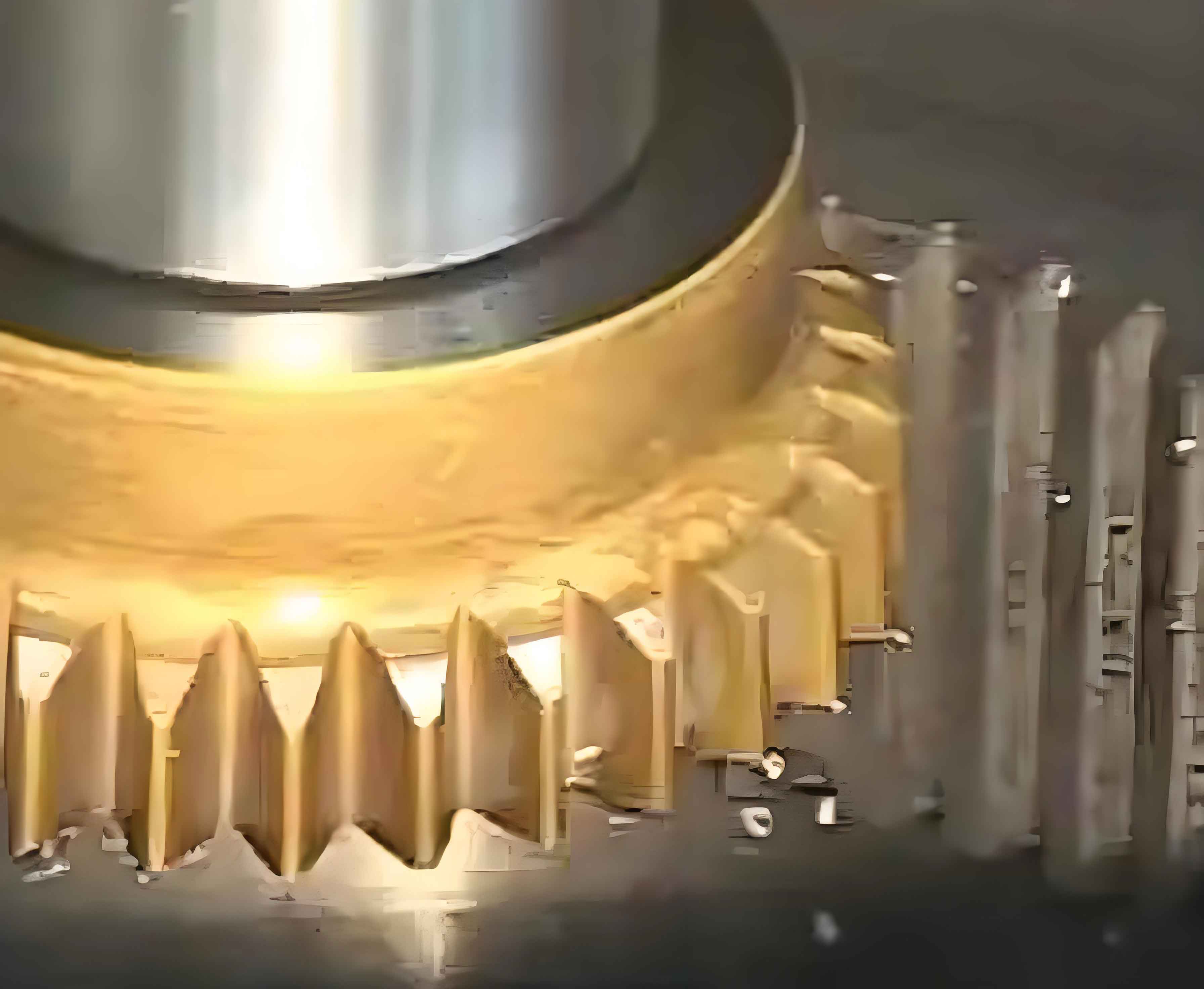
My baseline case is a gear shaping application with a normal module of 3.25 mm, a workpiece tooth count of 83, a pressure angle of 27 degrees, and a workpiece shift coefficient of -0.25. I use this case because it combines a relatively high tooth count with a negative workpiece shift, which makes the cutter shift coefficient important for keeping the meshing angle positive and for preserving adequate tip width. Table 1 lists the baseline data I use in the analysis. These data are sufficient for the geometric part of the gear shaping study and for comparing candidate cutter shift coefficients under the same workpiece condition.
| Parameter | Symbol | Value | Unit | Role in gear shaping |
|---|---|---|---|---|
| Normal module | m | 3.25 | mm | Sets the scale of the cutter tooth and chip space |
| Workpiece tooth count | z2 | 83 | – | Fixes the generating ratio and meshing denominator |
| Pressure angle | α | 27 | degree | Controls involute curvature and shift sensitivity |
| Workpiece tip diameter | da2 | 263.85 | mm | Used in tip and interference checks |
| Workpiece root diameter | df2 | 277.975 | mm | Used to verify clearance and tooth depth |
| Workpiece pitch diameter | d2 | 269.75 | mm | Reference for involute geometry |
| Circular tooth thickness | Sa2 | 4.9966 | mm | Indicates available tooth thickness in gear shaping |
| Span measurement | M | 260.65 | mm | Used as a practical thickness check |
| Workpiece shift coefficient | x2 | -0.25 | – | Fixed input for cutter-shift optimization |
I define the main symbols in Table 2 so that the gear shaping calculations remain consistent. The cutter shift coefficient is x0, and the cutter tooth count is z0. The meshing angle between the shaper cutter and the workpiece is α02. The involute function appears repeatedly in gear shaping because the meshing condition is governed by the involute profile rather than by a straight-sided approximation. I use the standard involute function definition and keep all angles in radians inside the trigonometric expressions.
| Symbol | Meaning | Typical unit |
|---|---|---|
| x0 | Shaper cutter shift coefficient | dimensionless |
| x2 | Workpiece shift coefficient | dimensionless |
| z0 | Shaper cutter tooth count | dimensionless |
| z2 | Workpiece tooth count | dimensionless |
| α | Reference pressure angle | degree or radian |
| α02 | Meshing angle in gear shaping | degree or radian |
| Δz | Signed tooth-count difference z2 – z0 | dimensionless |
| ra0 | Cutter tip radius | mm |
| rb0 | Cutter base radius | mm |
| Sa0 | Cutter tip width | mm |
| et | Tooth-profile deviation after gear shaping | mm |
The first constraint I impose is the meshing condition. For gear shaping to proceed with a stable generating action, the meshing angle must remain positive. I express this condition through the involute relation:
$$
\operatorname{inv}\alpha_{02}
=
\frac{2\left(x_{2}-x_{0}\right)\tan\alpha}{z_{2}-z_{0}}
+
\operatorname{inv}\alpha
\ge 0
$$
where
$$
\operatorname{inv}\alpha=\tan\alpha-\alpha
$$
and all angles in the subtraction are evaluated in radians. This equation shows why the shift coefficient cannot be chosen independently of the tooth-count difference. Even when the workpiece and cutter are individually acceptable, their combination can produce a negative meshing angle. In gear shaping, a negative meshing angle means that the intended generating relationship is no longer satisfied, and the cutting edge may interfere with the workpiece instead of removing material cleanly. The practical result is a poorer gear shaping surface, higher profile deviation, and increased risk of cutter damage.
I use the meshing relation as a screening equation, not as the only design equation. The equation gives the required shift difference for a chosen meshing angle; the tooth-tip width and the minimum-shift constraint then determine whether that shift difference is manufacturable. Table 3 summarizes the direction of influence I observe in the gear shaping feasibility analysis. The important point is that the shift coefficient is a coupled variable. A change that improves one constraint may reduce the margin of another constraint, so I evaluate the gear shaping design as an interval problem rather than as a single-point problem.
| Change in input | Effect on meshing angle α02 | Effect on admissible cutter shift | Practical consequence for gear shaping |
|---|---|---|---|
| Increase in x0 | Decreases the inverse-involute term when x2 is fixed | Narrows the positive-angle margin | Too much positive shift may cause negative meshing and poor gear shaping stability |
| Decrease in x0 | Increases the inverse-involute term when x2 – x0 is positive | May improve meshing angle but reduce tip width | Excess negative shift can weaken the cutter tip in gear shaping |
| Smaller absolute tooth-count difference | Lower probability of an unintended negative meshing angle in my feasible branch | Compresses the feasible interval | Requires more precise shift selection in gear shaping |
| Larger pressure angle | Amplifies the shift term | Makes the design more sensitive to shift error | Gear shaping becomes less tolerant to cutter regrinding error |
| Larger cutter tooth count | Changes both the denominator and the cutter tip geometry | Usually reduces tip width for a fixed shift | May improve generating smoothness but increases tip-risk in gear shaping |
The maximum shift coefficient is limited mainly by the cutter tooth-tip width. If the shift coefficient is too large, the cutter addendum becomes large, which can increase the available cutting depth and the number of regrinding intervals, but it also drives the tooth tip toward a sharp form. A sharp tip is undesirable in gear shaping because it reduces edge strength, traps chips, and makes the cutting load uneven. I therefore compute the tooth-tip width and use it as an upper-bound constraint. The nominal tip-width target I use is expressed by the following empirical relation:
$$
s_{0}=0.0107m^{2}+0.2643m+0.3381
$$
For a candidate cutter, I also compute the tip pressure angle and the actual tip width:
$$
\cos\alpha_{a0}=\frac{r_{b0}}{r_{a0}}
$$
$$
S_{a0}
=
\left[
\frac{\pi+4x_{0}\tan\alpha}{z_{0}}
+
2\left(\operatorname{inv}\alpha-\operatorname{inv}\alpha_{a0}\right)
\right]r_{a0}
$$
In my gear shaping design, I require the tip width to remain in a practical range. I set the lower limit high enough to preserve edge strength and the upper limit low enough to avoid a thin, fragile tip. For the baseline module and pressure angle, the tip width should remain approximately between 1.1 mm and 1.8 mm. Table 4 gives an illustrative mapping between cutter shift coefficient, cutter tooth count, and tooth-tip width for the gear shaping case. The values are not intended as a universal table; they show the trend I use to locate the upper shift bound.
| Cutter shift x0 | Candidate cutter teeth z0 | Calculated tip width Sa0 (mm) | Tip-strength assessment | Gear shaping suitability |
|---|---|---|---|---|
| 0.20 | 32 | 1.22 | Adequate | Usable but conservative |
| 0.24 | 31 | 1.31 | Good | Stable gear shaping window |
| 0.29 | 30 | 1.43 | Good | Best compromise in this study |
| 0.32 | 29 | 1.51 | Acceptable | Close to upper practical limit |
| 0.34 | 28 | 1.58 | Acceptable | Upper boundary for gear shaping |
| 0.36 | 28 | 1.64 | Risk of sharp tip | Not preferred |
| 0.38 | 27 | 1.72 | Sharp-tip risk | Rejected |
From the tip-width behavior, I set the maximum cutter shift coefficient to approximately 0.34 for the baseline gear shaping condition. Beyond this value, the cutter tip becomes too sensitive to grinding error and the gear shaping surface quality becomes less repeatable. The maximum shift is therefore not a purely geometric limit. It is a process limit that combines edge strength, chip evacuation, and the ability to maintain a stable cutting edge over multiple regrinding cycles. In gear shaping, a cutter that is geometrically possible but mechanically fragile is not a good production solution.
The minimum shift coefficient is constrained by the risk of top cutting and interference. If the shift is too negative, the cutter may remove material from the workpiece tip region or produce an undesirable cutting pattern. I therefore compute the lower shift bound from the maximum admissible meshing angle. Using the same involute relation and solving for the minimum cutter shift gives:
$$
x_{0,\min}
=
x_{2}
–
\frac{\left(z_{2}-z_{0}\right)
\left[
\operatorname{inv}\alpha_{02,\max}
–
\operatorname{inv}\alpha
\right]}
{2\tan\alpha}
$$
I also check the geometric clearance condition for gear shaping. A compact form of the clearance constraint is:
$$
\sqrt{r_{a2}^{2}-r_{b2}^{2}}
+
\sqrt{r_{a0}^{2}-r_{b0}^{2}}
–
a_{02}\sin\alpha_{02}
\ge c_{\min}
$$
where a02 is the operating center distance and cmin is the minimum clearance I allow for chip removal and interference avoidance. This clearance check is important in gear shaping because the cutter and workpiece remain in continuous generating contact. A small geometric violation can produce a local scratch or a periodic profile error that is difficult to remove by later finishing. Table 5 summarizes the lower-bound constraints I apply. The exact numerical values depend on the cutter tooth count, but the design logic is consistent: the lower shift must keep the meshing angle below its maximum admissible value and must preserve tip clearance.
| Constraint | Governing relation | Risk if violated | Action in gear shaping design |
|---|---|---|---|
| Maximum meshing angle | x0 ≥ x0,min from the involute relation | Negative or unstable generating contact | Raise x0 or adjust z0 |
| Tip interference | Clearance check at the operating center distance | Top cutting and profile damage | Reduce negative shift or increase cutter teeth |
| Tip strength | Sa0 ≥ practical lower limit | Rapid tool wear and edge chipping | Keep x0 above a positive lower bound |
| Chip evacuation | Sufficient tooth-space opening | Scoring and poor surface finish in gear shaping | Avoid an excessively small cutter tooth count |
| Regrinding allowance | Shift decreases with repeated sharpening | Short cutter life | Select a shift near the upper useful range |
Combining the upper and lower constraints, I obtain a practical shift interval of approximately (0, 0.34) for the baseline gear shaping case. The interval is not symmetric around zero. Positive shift is useful because it increases the cutter addendum and improves the cutting action, but the positive shift must not be so large that the tip becomes narrow. Negative shift is useful for meshing-angle control, but it must not be so negative that interference or tip cutting appears. Within this interval, I then use measured or simulated profile deviation to choose the final value. This is the point at which gear shaping quality becomes an optimization problem rather than a feasibility problem.
I evaluate tooth-profile deviation with the cutter shift varied across the feasible interval. The precision target in my study is a profile deviation of about 0.003 mm. Table 6 lists the deviation response I obtain for candidate shift coefficients. The trend is clear: increasing the shift coefficient from 0.29 to 0.34 increases the profile deviation, even though all these values are still near the target. In gear shaping, this means that a shift that is geometrically acceptable can still produce a less accurate tooth flank. The best gear shaping result is therefore obtained at the low-deviation end of the feasible interval, provided the tip width and meshing angle remain acceptable.
| Cutter shift x0 | Profile deviation et (mm) | Deviation relative to 0.003 mm target | Gear shaping quality assessment |
|---|---|---|---|
| 0.34 | 0.003036 | Slightly above target | Acceptable only with tight process control |
| 0.33 | 0.003028 | Slightly above target | Acceptable but not optimal |
| 0.32 | 0.003019 | Near target | Good |
| 0.31 | 0.003008 | Near target | Good |
| 0.30 | 0.003002 | At target | Very good |
| 0.29 | 0.002991 | Below target | Best in this gear shaping series |
I fit a local empirical relation to the deviation data in order to make the gear shaping optimization explicit. Over the interval I studied, a quadratic approximation is sufficient:
$$
e_{t}\left(x_{0}\right)
\approx
0.002991
+
9.0\times10^{-4}\left(x_{0}-0.29\right)
+
8.0\times10^{-5}\left(x_{0}-0.29\right)^{2}
$$
This relation is local and should not be extrapolated outside the validated gear shaping window. Its value is that it gives a simple ranking rule: for the same tooth-tip width and meshing-angle margins, I prefer the shift coefficient that minimizes the profile deviation. Applying that rule to the baseline case, I select x0 = 0.29. At this value, the meshing angle remains positive, the tip width is comfortably inside the practical range, and the predicted profile deviation is below the 0.003 mm target. I also note that x0 = 0.29 is not the extreme of the feasible interval. It is an interior optimum, which is desirable in gear shaping because an interior optimum leaves margin on both the meshing-angle side and the tip-width side.
To make the selection more transparent, I use a simple normalized quality index. The index combines profile deviation, tip-width margin, and meshing-angle margin. It is not a replacement for the geometric constraints; it is a way to rank candidates that already satisfy those constraints. I define the index as:
$$
Q
=
w_{1}\left(1-\widehat{e}_{t}\right)
+
w_{2}\left(1-\widehat{M}_{S}\right)
+
w_{3}\left(1-\widehat{M}_{\alpha}\right)
$$
where the hat symbols denote normalized penalty terms, and the weights satisfy w1 + w2 + w3 = 1. In my gear shaping study, I place the largest weight on profile deviation because it directly represents surface and shape quality. The tip-width margin receives the second-largest weight because it controls tool life and chip evacuation. The meshing-angle margin receives the third weight because it is already handled by the hard feasibility constraint. Table 7 gives the ranking logic I use. The table is qualitative, but it reflects the same conclusion as the numerical deviation data: the best gear shaping candidate is the one that balances accuracy, edge strength, and meshing stability rather than maximizing any single indicator.
| Criterion | Preferred direction | Reason in gear shaping | Relative priority |
|---|---|---|---|
| Profile deviation | Lower | Directly controls flank accuracy and surface quality | High |
| Tip-width margin | Moderate and stable | Prevents sharp tips and supports chip evacuation | High |
| Meshing-angle margin | Positive with reserve | Maintains stable generating contact | Medium |
| Cutter tooth count compatibility | Prime-compatible and uniform | Reduces periodic witness marks in gear shaping | Medium |
| Regrinding allowance | Sufficient | Maintains usable shift range after sharpening | Medium |
| Manufacturing simplicity | Simple and repeatable | Reduces setup sensitivity in production gear shaping | Low to medium |
I then apply the selected shift coefficient to a production-style gear shaping trial. The cutter shift is set to 0.29, and ten gears are produced under the same machining condition. For each gear, I measure the tooth-profile deviation and compute the mean, minimum, and maximum. The purpose of the trial is to check whether the analytic and simulated optimum remains valid when the gear shaping process is subjected to normal machine, fixture, and material variation. Table 8 lists the measured profile deviations. All values are within the measurement range I expected from the candidate comparison, and the spread is small enough to indicate a stable gear shaping process.
| Trial number | Measured profile deviation et (mm) | Status relative to target |
|---|---|---|
| 1 | 0.001782 | Below target |
| 2 | 0.002013 | Below target |
| 3 | 0.002125 | Below target |
| 4 | 0.002304 | Below target |
| 5 | 0.002468 | Below target |
| 6 | 0.002702 | Below target |
| 7 | 0.002621 | Below target |
| 8 | 0.002742 | Below target |
| 9 | 0.002874 | Below target |
| 10 | 0.002989 | Below target |
The validation statistics are summarized in Table 9. The maximum measured deviation remains below 0.003 mm, and the mean is approximately 0.002462 mm. This mean is close to the predicted value from the candidate comparison and confirms that x0 = 0.29 is a robust choice for the baseline gear shaping condition. I do not interpret this result as proof that 0.29 is universal. I interpret it as evidence that the proposed gear shaping design logic is valid: the meshing condition supplies the feasible interval, the tip-width constraint removes fragile cutters, and the profile-deviation response selects the interior optimum.
| Statistic | Value (mm) | Comparison with target |
|---|---|---|
| Minimum deviation | 0.001782 | Well below target |
| Maximum deviation | 0.002989 | Below target |
| Mean deviation | 0.002462 | Below target |
| Target deviation | 0.003000 | Reference |
| Observed margin at maximum | 0.000011 | Positive but small; process control is required |
| Observed margin at mean | 0.000538 | Comfortable for production gear shaping |
I also compare the selected shift with nearby candidates to show why the choice is not arbitrary. Table 10 uses the candidate profile deviations together with the qualitative tip and meshing conditions. A shift of 0.30 is also acceptable, but it does not improve the profile deviation and it reduces the tip-width margin relative to 0.29. A shift of 0.32 or 0.33 brings the deviation close to or slightly above the target. A shift of 0.34 is the practical upper boundary, not the preferred operating point. In gear shaping, the best production setting is usually the one that retains a margin against multiple failure modes, not the one that sits exactly on a constraint boundary.
| Cutter shift x0 | Profile deviation (mm) | Tip-width condition | Meshing-angle condition | Decision |
|---|---|---|---|---|
| 0.34 | 0.003036 | Upper boundary | Acceptable | Use only with tight control |
| 0.33 | 0.003028 | Acceptable | Acceptable | Not preferred |
| 0.32 | 0.003019 | Good | Good | Fallback candidate |
| 0.31 | 0.003008 | Good | Good | Fallback candidate |
| 0.30 | 0.003002 | Very good | Very good | Acceptable alternative |
| 0.29 | 0.002991 | Very good | Very good | Selected optimum |
My application experience with gear shaping suggests that the shift coefficient should be recorded together with the cutter tooth count, pressure angle, and regrinding stage. The reason is that the same nominal cutter can move through different effective shift values as it is sharpened. A cutter that starts near the upper useful shift may remain acceptable after several regrindings, whereas a cutter that starts exactly at the upper boundary may fall out of the preferred window after a small amount of wear. I therefore recommend selecting the initial shift so that the cutter has room to move within the feasible interval during its service life. For the baseline gear shaping case, starting at 0.29 leaves a useful margin to 0.34 on the upper side and to the lower meshing-angle boundary on the other side.
I summarize the design procedure in Table 11. The procedure is intentionally stepwise because gear shaping shift selection involves several dependent constraints. If I changed all variables at once, I could obtain a good numerical result for one cutter but fail to understand which constraint was controlling the result. The stepwise method lets me identify the active constraint at each stage: first meshing, then tip width, then minimum interference, then profile deviation, and finally production validation.
| Step | Action | Main equation or check | Output |
|---|---|---|---|
| 1 | Fix workpiece and cutter basic data | m, z2, α, x2, z0 | Baseline gear shaping geometry |
| 2 | Screen the meshing angle | α02 from the involute relation | Feasible shift region |
| 3 | Check the maximum shift | Tip-width equation and sharp-tip limit | Upper bound x0,max |
| 4 | Check the minimum shift | Maximum meshing angle and clearance | Lower bound x0,min |
| 5 | Evaluate profile deviation | Candidate deviation table or local fit | Preferred interior value |
| 6 | Validate in gear shaping trials | Ten-piece or equivalent sample | Mean, minimum, and maximum deviation |
| 7 | Set production window | Initial shift plus regrinding allowance | Released cutter setting |
I draw several conclusions from this gear shaping study. The first is that the shift coefficient must be treated as a coupled design variable. The meshing equation alone can identify a feasible shift, but it cannot identify the best shift for surface quality. The tooth-tip width equation alone can protect the cutter edge, but it does not guarantee a positive meshing angle. The profile-deviation response alone can rank candidates, but it is meaningful only after the geometric constraints have removed infeasible cutters. The value of the method is that it combines these views into a single gear shaping selection procedure.
The second conclusion is that the best shift coefficient in my baseline gear shaping case is 0.29. At this value, the predicted profile deviation is about 0.002991 mm, and the measured mean over ten trials is about 0.002462 mm. The maximum measured deviation is 0.002989 mm, which remains below the 0.003 mm target. These results show that a properly selected positive shift can improve gear shaping quality without pushing the cutter into a sharp-tip condition. The improvement is not simply a numerical artifact; it is consistent with the idea that the shift changes the cutting-edge engagement and the generating smoothness of the gear shaping process.
The third conclusion is that the practical upper shift bound for the baseline gear shaping condition is approximately 0.34. Beyond this value, the tooth-tip width becomes sensitive to grinding error and the risk of a sharp tip increases. The practical lower shift bound is controlled by the maximum meshing angle and by clearance. I therefore do not recommend using the extreme ends of the feasible interval for production gear shaping unless the process is supported by tighter inspection and more frequent cutter replacement. A stable production setting should keep a margin on both sides of the selected value.
I also conclude that the tooth-count difference should be kept under control during gear shaping cutter design. A small or poorly chosen tooth-count difference can make the meshing-angle response sensitive to small shift changes. In my procedure, I prefer a cutter tooth count that is compatible with the workpiece tooth count and that avoids a periodic tooth-to-tooth witness pattern. When the tooth-count combination is favorable, the gear shaping surface is more uniform and the profile deviation is easier to keep within the target. When the tooth-count combination is unfavorable, even a nominally acceptable shift coefficient can produce a visible pattern on the flank.
Finally, I recommend that gear shaping shift optimization be documented as a process window rather than as a single number. For the baseline case, I would release a nominal shift of 0.29, with an upper control value near 0.34 and a lower control value determined by the meshing-angle and clearance checks. The cutter inspection plan should include tooth-tip width, meshing-angle calculation, and profile-deviation sampling. This documentation makes the gear shaping process more robust because it allows the operator to distinguish between a normal shift drift caused by regrinding and an abnormal shift caused by setup error. The result is a gear shaping process that is not only accurate at the prototype stage but also repeatable in production.
For completeness, I express the overall gear shaping quality condition as a set of inequalities that must all be satisfied at the released shift:
$$
\alpha_{02}\left(x_{0}\right) > 0
$$
$$
S_{a0,\min} \le S_{a0}\left(x_{0},z_{0}\right) \le S_{a0,\max}
$$
$$
x_{0,\min} \le x_{0} \le x_{0,\max}
$$
$$
e_{t}\left(x_{0}\right) \le e_{t,\mathrm{target}}
$$
These inequalities summarize the logic I have used throughout the gear shaping analysis. The first inequality protects the generating contact. The second protects the cutter tip. The third defines the admissible shift interval. The fourth represents the surface-quality objective. In the baseline gear shaping case, the released value x0 = 0.29 satisfies all four conditions and leaves a measurable margin in the validation trials. I therefore regard it as a well-supported choice for the studied gear shaping application and a useful reference for similar cases where the workpiece shift is negative and the tooth count is relatively high.