
As an engineering team specializing in heavy machinery components, we have long focused on the manufacturing challenges associated with critical parts like the gear shaft. In the context of tractor systems, the gear shaft is a pivotal element that transmits torque and motion, ensuring efficient power delivery. Our experience has shown that traditional free forging methods often fall short in meeting the stringent technical specifications for such gear shafts, leading to excessive machining allowances and production bottlenecks. This article details our development and implementation of an enhanced forging process that addresses these issues, emphasizing the gear shaft as a central component. We will explore the technical nuances, advantages, and practical applications of this method, supported by tables and formulas to summarize key insights.
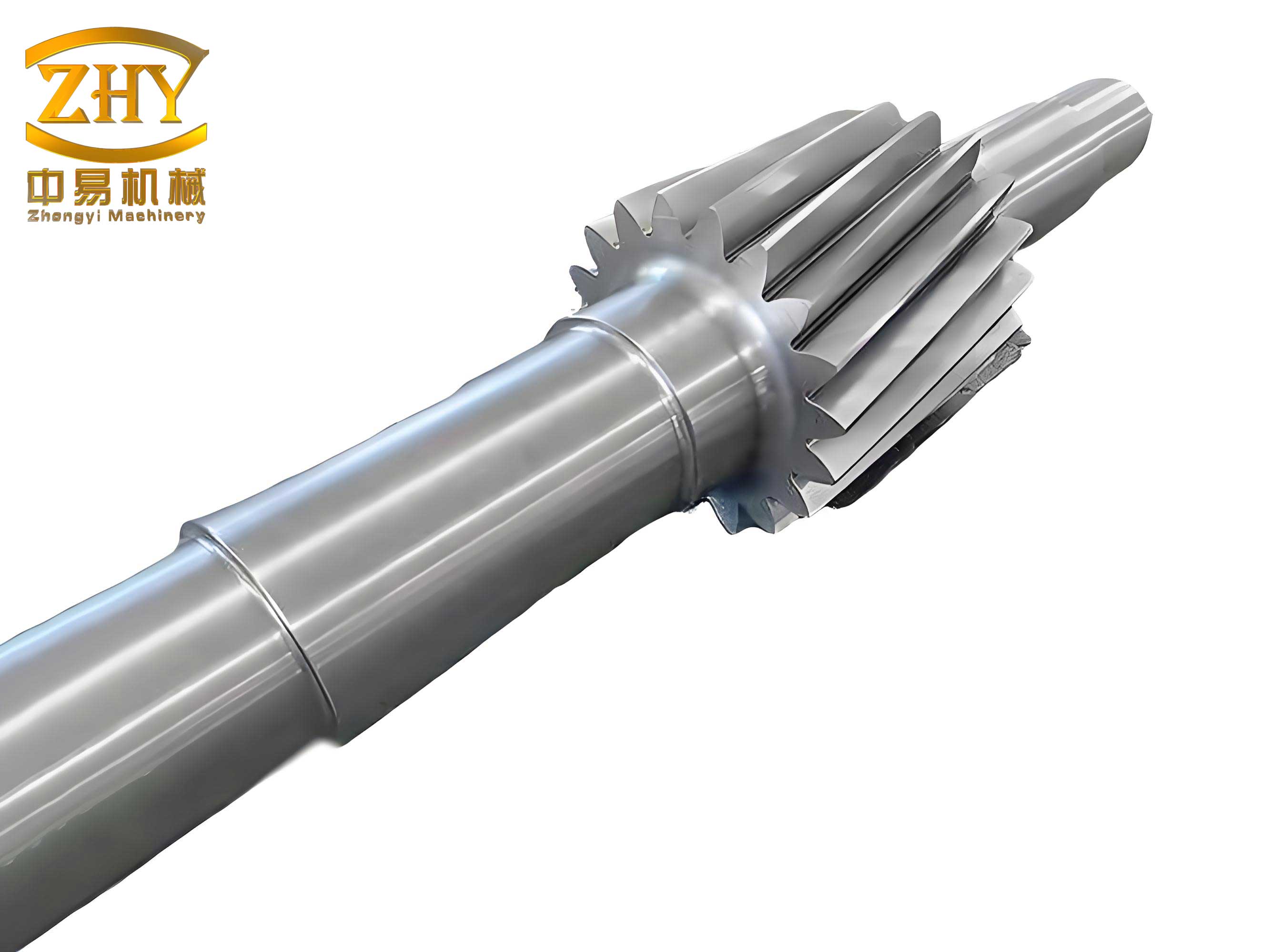
The gear shaft, particularly in agricultural machinery like tractors, must withstand high loads and operate with precision. In our initial assessments, we observed that conventional free forging techniques for producing gear shafts resulted in inconsistent dimensional accuracy and poor material utilization. The large machining allowances required not only increased material waste but also slowed down production cycles, making it difficult to keep pace with demand. This prompted us to innovate a two-heat forging process using a steam hammer, which has revolutionized our approach to manufacturing gear shafts. This new methodology leverages the principles of free forging combined with die-assisted forming, offering a viable solution in the absence of large-scale模锻锤 equipment.
To understand the core of our process, let’s delve into the material considerations. The gear shaft is typically made from medium-carbon steels or alloy steels, which provide the necessary strength and durability. The material properties can be expressed through formulas such as the yield strength $\sigma_y$ and ultimate tensile strength $\sigma_u$, which are critical for forging simulations. For instance, the flow stress during forging can be modeled using the Hollomon equation: $$\sigma = K \epsilon^n$$ where $\sigma$ is the true stress, $K$ is the strength coefficient, $\epsilon$ is the true strain, and $n$ is the strain-hardening exponent. These parameters guide our selection of forging temperatures and forces, ensuring optimal deformation for the gear shaft.
Our new forging process for the gear shaft involves two distinct heats, each with specific operations. The first heat focuses on preliminary shaping: we perform clamping and marking (夹印) followed by forming the two end shafts (甩二端轴). This step is crucial for establishing the basic geometry and aligning the material for subsequent forging. The second heat completes the成型 to the final锻件图, achieving the desired dimensions and tolerances. By reducing the number of heats, we minimize energy consumption and thermal damage to the gear shaft material. The following table summarizes the key steps and parameters:
| Heat Number | Operation | Temperature Range (°C) | Hammer Force (tons) | Key Outcome for Gear Shaft |
|---|---|---|---|---|
| 1 | Clamping and Marking (夹印) | 1150-1200 | 2 | Initial alignment and reduction |
| 1 | Forming Two End Shafts (甩二端轴) | 1100-1150 | 2 | Pre-shaping of shaft ends |
| 2 | Final成型 to锻件图 | 1050-1100 | 2 | Accurate gear shaft profile |
This structured approach ensures that each stage contributes to the overall integrity of the gear shaft. The clamping operation, for example, involves applying localized pressure to create reference points, which aids in maintaining concentricity—a critical requirement for gear shafts to function smoothly in transmission systems. The forming of end shafts is achieved through controlled hammer blows, with the force distribution calculated using formulas like: $$F = \sigma_y \cdot A$$ where $F$ is the forging force, $\sigma_y$ is the yield strength at forging temperature, and $A$ is the contact area. By optimizing these parameters, we reduce the risk of defects such as folds or cracks in the gear shaft.
One of the standout features of our new process is its operational simplicity. The tools required for clamping and forming are relatively easy to manufacture and maintain, which lowers production costs and downtime. This is especially beneficial for small to medium-sized enterprises that may not have access to advanced模锻锤. The design of these tools incorporates principles of modularity, allowing quick adjustments for different gear shaft specifications. We have developed a set of standard tooling profiles that can be adapted through minor modifications, as shown in the table below:
| Tool Component | Function | Material | Lifecycle (Number of Forging Cycles) | Impact on Gear Shaft Quality |
|---|---|---|---|---|
| Clamping Die | Holds and marks坯料 | H13 Tool Steel | 5000-6000 | Ensures precise initial shaping |
| End Shaft Forming Die | Shapes the two ends of the gear shaft | D2 Tool Steel | 4000-5000 | Reduces machining allowance |
| Final成型 Die | Achieves final gear shaft dimensions | H11 Tool Steel | 3000-4000 | Guarantees dimensional accuracy |
The concentricity of the gear shaft is paramount, as any deviation can lead to vibration and premature failure in tractor applications. Our process inherently promotes concentricity by using the same reference points throughout both heats. The alignment error $\Delta$ can be quantified using geometric formulas: $$\Delta = \sqrt{(x_1 – x_2)^2 + (y_1 – y_2)^2}$$ where $(x_1, y_1)$ and $(x_2, y_2)$ are coordinates from the clamping marks. By keeping $\Delta$ within tight tolerances (typically less than 0.1 mm for gear shafts), we ensure that the final product meets industry standards. Additionally, the use of胎模揪 (die-assisted free forging) allows for better control over material flow, which is expressed through the strain rate $\dot{\epsilon}$: $$\dot{\epsilon} = \frac{d\epsilon}{dt}$$ where $t$ is time. Controlling $\dot{\epsilon}$ during hammer impacts minimizes internal stresses in the gear shaft.
From a production standpoint, this new forging process for gear shafts offers significant advantages in batch manufacturing. The reduced火次 (number of heats) translates to faster cycle times and higher throughput. We have observed a production increase of up to 30% compared to traditional methods, enabling us to meet growing demand for tractor components. The table below compares the old and new processes for gear shaft forging:
| Aspect | Traditional Free Forging | New Two-Heat Process | Improvement for Gear Shaft |
|---|---|---|---|
| Number of Heats | 3-4 | 2 | Reduced energy use and time |
| Machining Allowance (mm) | 5-8 | 2-4 | Less material waste |
| Concentricity Tolerance (mm) | 0.2-0.3 | 0.05-0.1 | Better performance in assembly |
| Tooling Complexity | High | Low to Moderate | Lower maintenance costs |
| Production Rate (units per hour) | 10-15 | 20-25 | Increased output for gear shafts |
To further optimize the gear shaft forging process, we have integrated computational models that simulate material behavior. The finite element method (FEM) allows us to predict deformation patterns and stress distributions. The governing equation for thermo-mechanical analysis during forging is: $$\rho c_p \frac{\partial T}{\partial t} = \nabla \cdot (k \nabla T) + \sigma : \dot{\epsilon}$$ where $\rho$ is density, $c_p$ is specific heat, $T$ is temperature, $k$ is thermal conductivity, and $\sigma : \dot{\epsilon}$ represents the heat generation due to plastic work. These simulations help us fine-tune parameters like hammer speed and dwell time, ensuring that the gear shaft achieves the desired metallurgical properties, such as grain refinement and hardness uniformity.
The material savings achieved through this process are substantial. For a typical gear shaft with an initial坯料 weight of 50 kg, the traditional method might require machining to remove 8 kg of material, whereas our new process reduces this to 3 kg. This not only cuts costs but also aligns with sustainable manufacturing practices. The volumetric strain $\epsilon_v$ during forging can be calculated as: $$\epsilon_v = \frac{\Delta V}{V_0}$$ where $V_0$ is the initial volume and $\Delta V$ is the volume change. By minimizing $\epsilon_v$ through precise forming, we enhance material utilization for each gear shaft.
In terms of tooling maintenance, the simplicity of our dies means that repairs can be carried out in-house with minimal downtime. We have established a preventive maintenance schedule based on the number of forging cycles, using wear models such as Archard’s equation: $$W = K_w \frac{F_n \cdot s}{H}$$ where $W$ is wear volume, $K_w$ is a wear coefficient, $F_n$ is the normal force, $s$ is sliding distance, and $H$ is material hardness. This proactive approach ensures consistent quality for every gear shaft produced.
The applicability of this forging process extends beyond tractor gear shafts to other automotive and industrial components. However, the gear shaft remains a prime example due to its complex geometry and high performance requirements. We have successfully implemented this method in batch production runs of over 10,000 units, with defect rates below 0.5%. The key to this success lies in the integration of empirical knowledge with analytical tools, creating a robust manufacturing framework.
Looking ahead, we are exploring further enhancements, such as incorporating closed-die forging elements to achieve even tighter tolerances for gear shafts. The potential for automation using robotic hammer systems could also increase efficiency. The fundamental equation for forging force in closed-die scenarios is: $$F = C \cdot \sigma_y \cdot A_f$$ where $C$ is a constraint factor (typically 2-3 for complex shapes like gear shafts), and $A_f$ is the projected area of the forging. By advancing these techniques, we aim to set new benchmarks in gear shaft manufacturing.
In conclusion, our innovative two-heat forging process represents a significant leap forward in the production of high-quality gear shafts. By addressing the limitations of traditional free forging, we have achieved improvements in accuracy, efficiency, and cost-effectiveness. The gear shaft, as a critical component in tractors and beyond, benefits from this methodology through enhanced performance and reliability. We believe that this approach can serve as a model for similar manufacturing challenges, leveraging the synergy between simple tools and advanced process control. Through continuous refinement and adaptation, we are committed to pushing the boundaries of what is possible in gear shaft forging.