
In my extensive experience within the gear manufacturing industry, I have come to recognize the pivotal role that fixturing plays in the precision machining of components. The system encompassing “machine tool – cutting tool – fixture – workpiece” represents a delicate interplay of static and dynamic geometric relationships. Within this system, the fixture acts as the critical interface, and its design directly dictates whether the final workpiece meets the stringent accuracy requirements of the engineering drawings. This is especially true for the gear shaving process, which is often the final finishing operation for gears not destined for grinding. The quality of the gear shaving outcome is paramount, as it determines the final profile and lead accuracy of the gear teeth. My focus here is to delve into the design and structural analysis of the shaving arbor, a core fixture element, sharing insights from firsthand design and troubleshooting endeavors.
The gear shaving process is employed to refine tooth flanks after hobbing or shaping, improving surface finish and correcting minor geometrical deviations. The fundamental requirement for a successful shave is the precise location and clamping of the gear blank. Any inaccuracy in the fixture is magnified and transferred directly onto the tooth geometry. Consider a typical gear component where the gear shaving operation uses the internal spline minor diameter (e.g., Ø81.3 H7) as the primary locating datum. The gear is clamped between two large face surfaces on the arbor assembly. The post-shaving quality specifications are demanding: a surface roughness of Ra ≤ 1.6 μm, a total profile form error Fα ≤ 0.022 mm, and a lead angle error Fβ ≤ 0.018 mm. Furthermore, the profile and lead are often specified to have a specific modified shape, such as a “K” chart pattern. Achieving this consistently is the challenge.
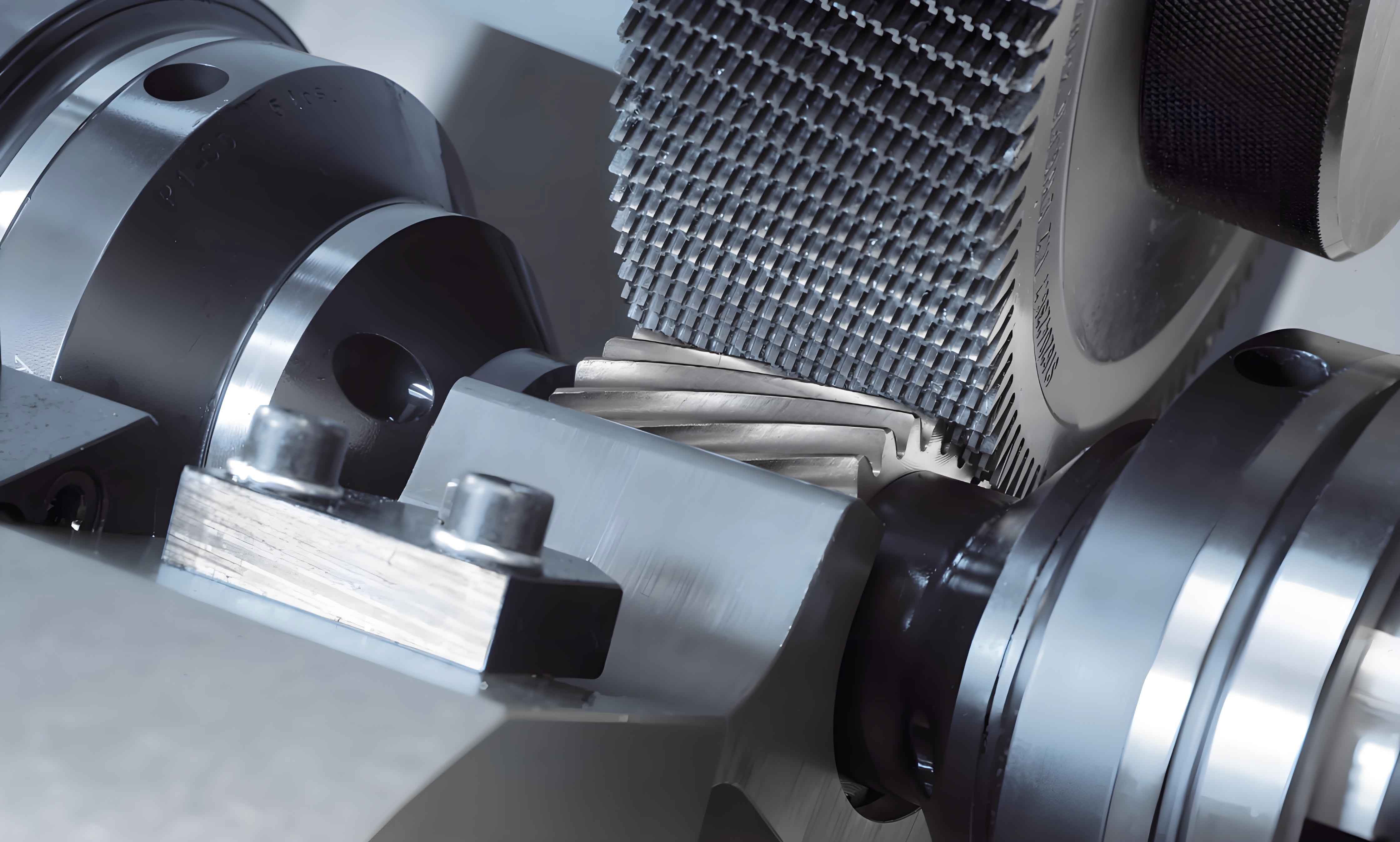
The most common shaving arbor design I have encountered, and initially worked with, consists of a central mandrel (shaft) and two clamping pressure pads or end caps. The gear is mounted on the mandrel’s locating diameter, and the two pads are tightened against the gear’s faces to secure it axially. The critical geometric feature of this assembly is the perpendicularity and flatness of the clamping faces relative to the mandrel’s axis. The conventional manufacturing procedure for this arbor involves assembling the mandrel and pads and then grinding their two opposing clamping faces in a single setup between centers. The goal is to achieve a face runout, or total indicated runout (TIR), of less than 0.01 mm. This runout (ΔT) can be conceptually defined as the maximum axial displacement of the face surface as it rotates, which if not controlled, introduces a tilt to the mounted gear. The error introduced can be modeled as an angular misalignment θ, related to the runout ΔT and the clamping diameter D:
$$ \theta \approx \arctan\left(\frac{\Delta T}{D}\right) $$
For a small angle, this approximates to $$ \theta \approx \frac{\Delta T}{D} $$ radians.
This angular error directly propagates into the gear’s axis during gear shaving, causing inconsistent tooth lead (Fβ) and, due to the nature of the shaving cutter interaction, profile errors (Fα). The traditional assembly for finish grinding is shown conceptually below, highlighting a fundamental oversight.
| Component | Traditional Design Grinding Setup | Critical Issue |
|---|---|---|
| Mandrel | Ground between centers, contacting pad on small non-functional pilot. | Manufacturing datum (small pilot contact faces) is not the same as the functional datum (large clamping faces). |
| Pressure Pad | Ground while pressed against mandrel’s small pilot face. | Runout of the large clamping face is not guaranteed after reassembly in any random clocking position. |
The core problem, which I identified through repeated analysis of inconsistent gear shaving results, is the discrepancy between the manufacturing datum and the functional, or use, datum. During the final grinding operation, the mandrel and pads are assembled such that their small, non-functional pilot faces are in contact. The grinding machine centers locate on the mandrel’s center holes, and the large clamping faces are ground. While this ensures the two large faces are parallel to each other and perpendicular to the axis in that specific assembled state, it does not guarantee their individual runout relative to the axis. When the arbor is disassembled for cleaning or maintenance and then reassembled to load a workpiece, the relative clocking position between the mandrel and pads changes. Since the small pilot faces were not precision-ground for runout, this change in angular orientation introduces a random, unmeasured, and often significant face runout error into the system. The functional datum—the large clamping faces—now has a runout that is not controlled, violating a basic principle of precision fixture design: the manufacturing and use datums must be identical.
The consequences of this design oversight in gear shaving are severe and systematic. The variable face runout causes the gear blank to be tilted at a different, unpredictable angle each time it is clamped. During the gear shaving process, this manifests as inconsistent tooth-tooth variation. On one tooth, the profile might show a positive deviation at the root and negative at the tip, while on another tooth, 180 degrees opposite, the error pattern would be reversed (negative at root, positive at tip). The lead angle would similarly vary. This inconsistency is a hallmark of a fixture-induced error rather than a machine or tooling issue. The data from such a process is chaotic, as summarized below for a batch of gears shaved with the traditional arbor:
| Gear Sample | Tooth 1 Profile Error (Fα in mm) | Tooth 1 Lead Error (Fβ in mm) | Tooth 10 Profile Error (Fα in mm) | Tooth 10 Lead Error (Fβ in mm) | Profile Consistency |
|---|---|---|---|---|---|
| 1 | +0.015 / -0.020 | +0.012 | -0.018 / +0.017 | -0.010 | Poor |
| 2 | -0.010 / +0.015 | -0.014 | +0.012 / -0.019 | +0.011 | Poor |
| 3 | +0.005 / -0.025 | +0.008 | -0.022 / +0.008 | -0.015 | Poor |
The mathematical representation of the error introduced can be expanded. If we denote the runout error at the large clamping face of the mandrel as $$ \Delta M $$ and the runout error at the clamping face of the pressure pad as $$ \Delta P $$, and these errors are not correlated due to the random assembly, the effective tilt error $$ \theta_{eff} $$ imparted to the workpiece becomes a function of their vectorial sum at the clamping diameter. Assuming the errors are sinusoidal, the combined effect for a given assembly clocking angle φ is:
$$ \Delta T_{eff}(\phi) = \sqrt{ \Delta M^2 + \Delta P^2 + 2 \cdot \Delta M \cdot \Delta P \cdot \cos(\phi + \phi_0) } $$
where $$ \phi_0 $$ is a phase offset. The resulting lead error Fβ on the gear is approximately proportional to this effective runout over the face width. For a gear with face width B, the approximate lead error is:
$$ F\beta \approx B \cdot \theta_{eff} \approx B \cdot \frac{\Delta T_{eff}}{D_{clamp}} $$
This clearly shows how an uncontrolled ΔTeff leads directly to an uncontrolled and variable Fβ error in the gear shaving output.
Driven by the need for consistent, high-quality gear shaving results, I led a redesign of the shaving arbor. The principle was simple yet transformative: enforce identity between the manufacturing datum and the functional datum. This meant that the surfaces which contact each other during the final precision grinding operation must be the same surfaces that define the workpiece location during use. The revised design introduced two key modifications to both the mandrel and the pressure pad.
First, on the mandrel, the small pilot diameter that contacts the pad was now specified with a tight runout tolerance relative to the centerline, and its face was required to have a fine surface finish. This surface becomes a precise manufacturing datum. Second, and crucially, the pressure pad was redesigned to incorporate a precise, short (e.g., 2mm) pilot step. This step mates with a corresponding counterbore on the mandrel’s large face (or vice-versa, depending on design). The critical clamping face of the pad is now ground while this pilot step is seated against the newly precision-finished pilot face of the mandrel. This setup is illustrated in the comparison table below.
| Feature | Traditional Design | Improved Design | Rationale |
|---|---|---|---|
| Mandrel Pilot Face | Unspecified roughness & runout. | Specified roughness (e.g., Ra 0.8 μm), runout ≤ 0.005 mm. | Creates a precise, repeatable axial manufacturing datum. |
| Pressure Pad | Flat back, contacts mandrel pilot over large area. | Includes a machined pilot step (e.g., 2mm tall) with tight diameter tolerance. | Provides a positive location feature that enforces concentricity and repeatable axial contact. |
| Grinding Setup Datum | Contact on non-functional small faces. | Contact on the functional pilot step and precision pilot face. | Manufacturing datum (step/face contact) is identical to the assembly datum during use. |
| Guaranteed Runout | Only parallel faces guaranteed in one assembly state. | Individual face runout (TIR) of each clamping component is guaranteed ≤ 0.01 mm. | Runout is a controlled property of each part, independent of assembly clocking. |
The manufacturing process for the improved arbor is now a two-stage precision operation. First, the mandrel’s locating diameter and its new precision pilot face are ground relative to its center holes. Second, the pressure pad’s pilot step is machined, and then its clamping face is finish-ground while it is assembled onto the mandrel using the new pilot features as the locating datum. This ensures that the runout of the pad’s clamping face is directly referenced to the mandrel’s axis. The relationship can be formalized. Let $$ R_{m} $$ be the runout of the mandrel’s clamping face, and $$ R_{p} $$ be the runout of the pad’s clamping face, both measured relative to the common axis defined by the mandrel’s centers and the pilot interface. In the improved design, both $$ R_{m} $$ and $$ R_{p} $$ are independently controlled to be ≤ 0.01 mm. The total face runout in any assembly is now simply the sum of their magnitudes, which remains bounded and, more importantly, predictable.
$$ \Delta T_{total} \leq R_{m} + R_{p} \leq 0.02 \, \text{mm} $$
In practice, with careful machining, $$ \Delta T_{total} $$ is often held below 0.01 mm. The tilt error θ is now a constant, minimal value, leading to consistent gear shaving geometry. The effectiveness of this redesign was validated through extensive production trials. Gears processed with the new arbor showed remarkable consistency in tooth geometry. The profile and lead charts from all teeth on a gear were nearly identical, conforming tightly to the specified “K” shape. Statistical process control data showed a drastic reduction in variation.
| Performance Metric | With Traditional Arbor | With Improved Arbor | Improvement |
|---|---|---|---|
| Profile Error Range (Fα, mm) | 0.030 – 0.045 | 0.015 – 0.022 | ~50% reduction |
| Lead Error Range (Fβ, mm) | 0.020 – 0.030 | 0.010 – 0.018 | ~40% reduction |
| Tooth-to-Tooth Consistency (σ of Fα) | 0.008 mm | 0.002 mm | 4x more consistent |
| Surface Roughness (Ra, μm) | 1.8 – 2.5 | 1.2 – 1.6 | More stable, meets spec |
| Process Capability (Cpk for Fα) | ~0.8 | ~1.5 | Shift from marginal to capable |
The underlying reason for the improved surface finish in gear shaving is the elimination of erratic workpiece motion. A stable, precisely located gear blank allows the shaving cutter to perform a consistent, uninterrupted finishing pass across the entire tooth flank. The cutting forces remain stable, minimizing chatter and yielding a superior surface texture. This redesign principle—datum identity—has profound implications beyond gear shaving fixtures. It is a fundamental axiom in precision tooling design: the surfaces used to establish geometry during manufacturing must be the same surfaces that establish location during functional use. Any compromise on this principle introduces unconstrained degrees of freedom and unpredictable error.
In reflecting on this journey of analyzing and refining the gear shaving arbor, several key formulas and relationships crystallize the learning. The face runout tolerance (T) translates to a maximum permissible angular error (α_max) for a given clamping radius (R_clamp):
$$ \alpha_{max} = \frac{T}{R_{clamp}} $$
For a gear with face width W, the maximum lead error (ΔL) contributed solely by this tilt is:
$$ \Delta L = W \cdot \tan(\alpha_{max}) \approx W \cdot \alpha_{max} = \frac{W \cdot T}{R_{clamp}} $$
If the specification calls for ΔL ≤ Fβ_spec, then the required fixture face runout tolerance is:
$$ T \leq \frac{F\beta_{spec} \cdot R_{clamp}}{W} $$
Plugging in typical values (Fβ_spec = 0.018 mm, R_clamp = 40 mm, W = 30 mm) gives T ≤ 0.024 mm. While this seems lenient, the need for consistency and the contribution of other error sources (e.g., machine tool, cutter) dictate a much tighter fixture tolerance, such as 0.01 mm. Furthermore, for profile accuracy during gear shaving, the relationship is more complex as it involves the relative motion between the cutter and the tilted workpiece. A simplified view considers the effective base circle offset caused by tilt, which modifies the involute generation. The profile slope deviation fHα can be related to the tilt angle and the gear’s pressure angle φ:
$$ fH\alpha \propto \alpha_{max} \cdot \tan(\phi) $$
This underscores that controlling α_max is essential for controlling both lead and profile in gear shaving.
The implementation of the improved arbor design required careful attention to material selection and heat treatment to ensure long-term stability of the precision datum surfaces. Using hardened tool steel (e.g., case-hardened alloy steel) for the mandrel and pads ensures resistance to wear and deformation under clamping loads. The design also incorporated features for easy cleaning of the pilot interfaces to prevent chip accumulation, which could defeat the precision location. The success of this project has led to the standardization of this datum-identity principle across all critical fixturing for finishing operations, not just for gear shaving but also for honing, grinding, and inspection setups.
In conclusion, the journey from diagnosing inconsistent gear shaving results to implementing a robust solution reinforced a core tenet of mechanical design. The analysis revealed that a seemingly minor oversight in fixture design—allowing the manufacturing and functional datums to diverge—can have catastrophic effects on product quality. By structurally modifying the shaving arbor to enforce datum identity through precise pilot features, the variability was eliminated. The gear shaving process transformed from a source of scrap and rework into a stable, capable, and predictable operation. This case serves as a powerful reminder that in the world of precision manufacturing, the integrity of the fixture is not just about strength and rigidity, but fundamentally about the rigorous control of geometric relationships from the first machining cut to the final part clamping. Every future fixture I design for gear shaving or any other precision process will embody this principle as its foundation, ensuring that the workpiece, once clamped, is a true and unwavering extension of the machine tool’s intended geometry.