
All teeth on helical cylindrical gears are the same and have unified characteristics. The normal tooth profile will be generated from the end tooth profile of the spiral cylinder. Take involute standard helical cylindrical gear as an example.
The profile of helical cylindrical gear on the end face is involute, so the expression in helical cylindrical gear can be used directly. For example, the addendum circle diameter of helical cylindrical gear is da = 84.56mm, the number of teeth is Z = 32, the tooth width is b = 30mm, the normal modulus is Mn = 2.5mm, the helix angle Bata on the addendum circle is 25 °, and the rotation direction is left rotation. Select the expression tool in UG and enter the involute expression:


What is special is that the second half of the above formula adopts matrix transformation to solve the problem of involute profile symmetry, which greatly improves the accuracy compared with the manual way of choosing the rotation angle, and lays a good foundation for the accurate drawing of the profile of helical cylindrical gear. Moreover, because the expression tool inside UG is adopted, the programming processing is avoided and the work efficiency is improved.
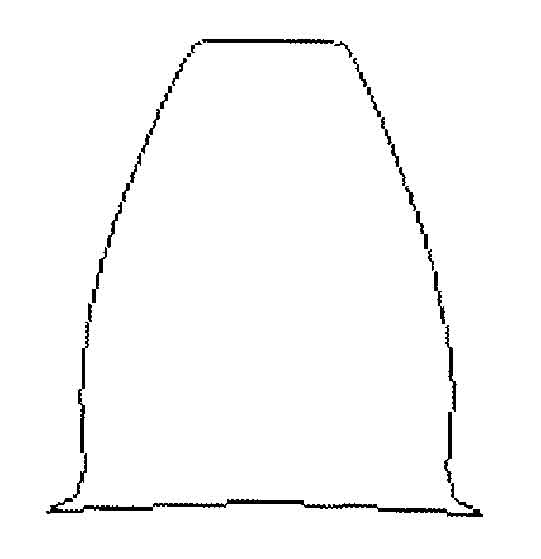
Then insert the regular curve with the coordinate origin as the reference point according to the by equation method of law curve in UG. UG will automatically calculate x0 and Y0 values and draw involute, and the z-axis coordinate is 0. Take the y-axis as the symmetry center, mirror the involute to obtain two tooth side contours. All parameters in this equation can be modified at any time, and the generated curve will change accordingly. Taking the working coordinate origin as the benchmark, trim it with the tooth top circle and tooth root circle, and deal with the transition fillet at the tooth top and tooth root. The tooth profile of the end face of the helical cylindrical gear is shown in the figure.