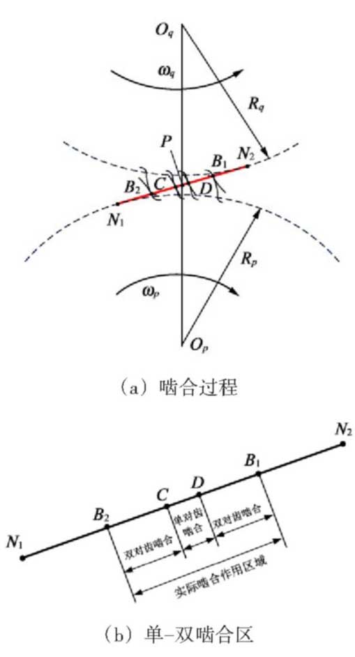
According to the engagement principle of involute spur gear, when a pair of involute profiles engage and drive, any engagement action point on the profile should fall on the internal common tangent of the base circle of the gear secondary body.

(meshing line) as shown in Figure 1.In the actual engagement process, according to the geometric engagement limit analysis method, the driving gear P and driven gear Q begin to mesh at point B2 (the driving gear root drives the top of the driven gear to engage on the engagement line), i.e. the engagement starting point, and at point B1 its teeth are disengaged and out (the top of the driving gear drives the root of the driven gear to engage on the engagement line), i.e. the engagement ending point.Visible actual engagement range of a pair of teeth on line

Inner.To ensure the meshing smoothness of common spur gear pair, the range of its overlap degree E is generally 1 <E < 2. There must be double-single-double alternating engagement between adjacent teeth during the process of rodenting and rodenting, as shown in Figure 1(b).Based on the above engagement characteristics, the calculation of TVMS for a pair of healthy gears can be simplified to the calculation of any tooth in the engagement line segment.

The generated meshing stiffness is obtained by cycling over time.Calculate the actual engagement action line segment of any tooth with the active gear P as the calculation reference

The formula for the length and angle range of internal action is
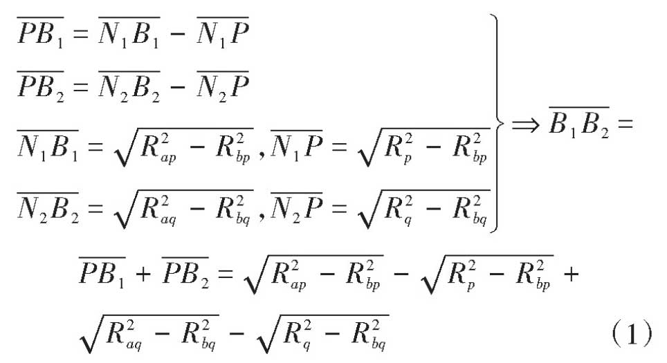
Further simplification is available
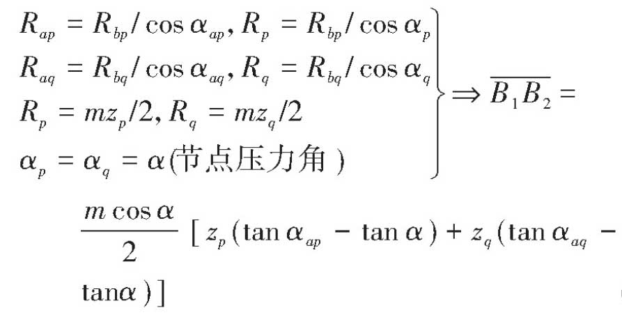
Due to line segment

And (2) combined calculation
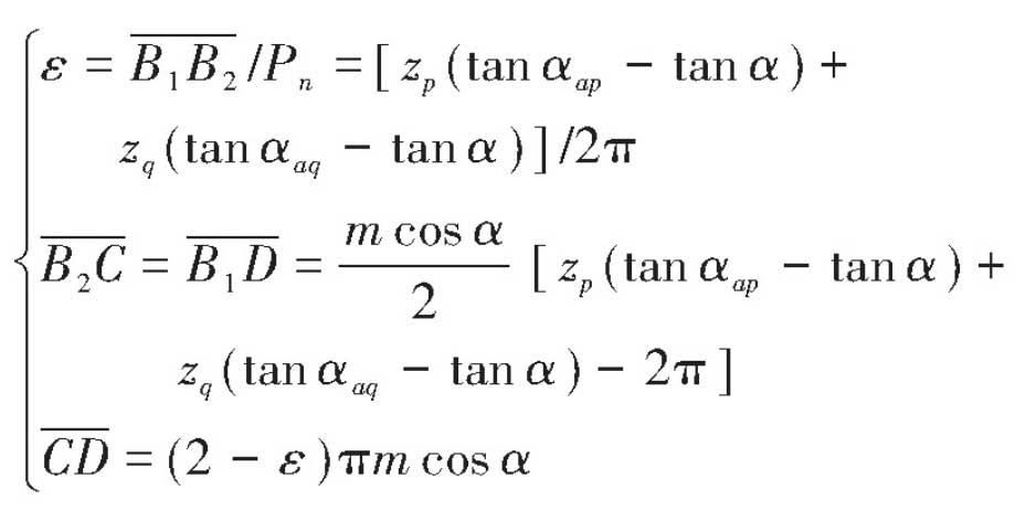
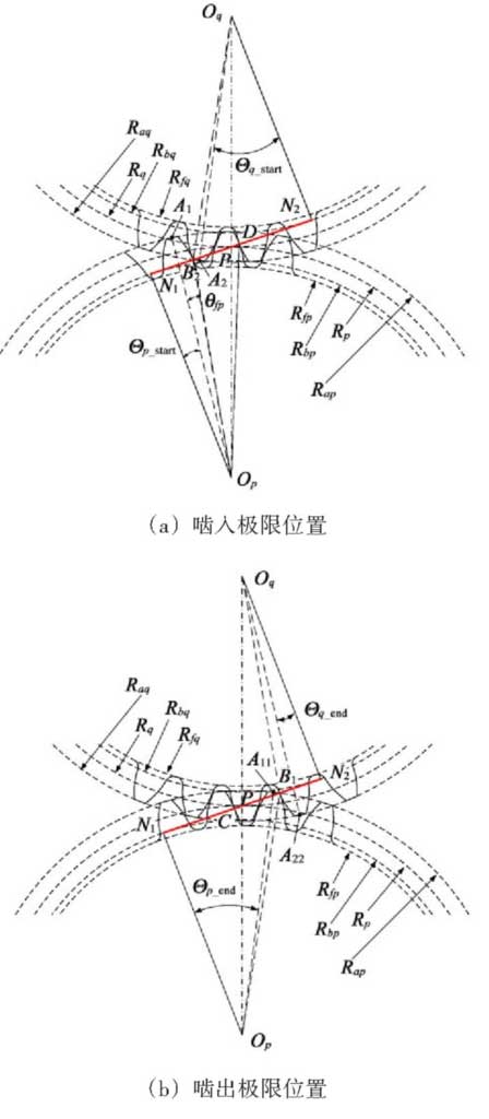
Figure 2 shows a schematic representation of the rodent and the rodent of any tooth profile for ease of engagement.

Internal calculation of gear rotation angle boundary, setting

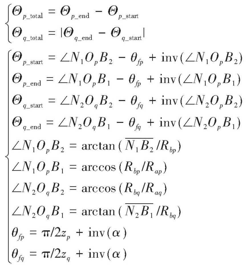
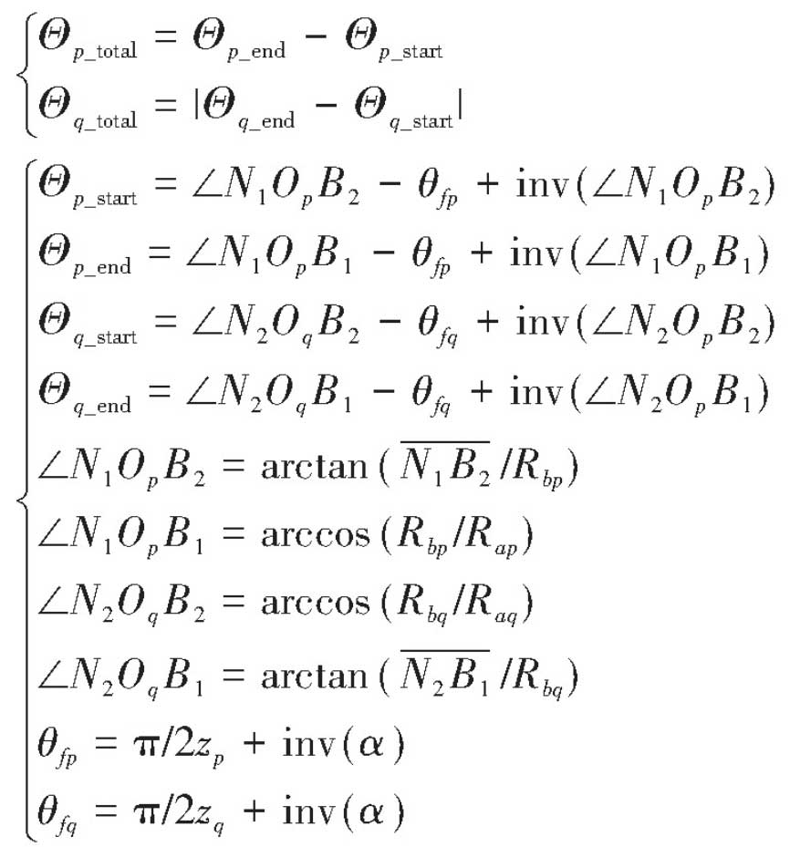
For the boundary reference line and p=0 and q=0 at the beginning of the meshing point B2 for the master and slave teeth, the meshing line

The total engagement angle is shown in Formula (4), the related parameters in Formula (4) are derived and calculated in Formula (5), and the geometric diagram is shown in Figure 2.When the meshing action of tooth profile is from point B2 to point D,

At this point, the meshing angle of the gear P changes to the arc angle p0=2pi/zp corresponding to the pitch, and according to the double-single-double meshing alternation shown in Figure 1(b), the meshing action line of any gear can be calculated from scratching to scratching.

The upper single and double engagement boundary is shown in Eq. (6).
