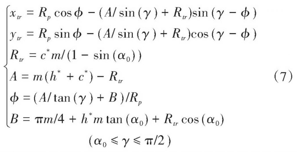
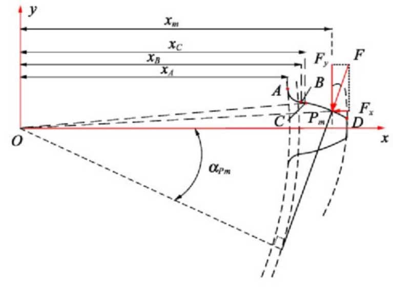
The profile shape of standard involute gears generally consists of two sections, i.e. transition rounded curve AB and involute curve BD, as shown in the figure.According to the function of meshing geometry position of gear pair, involute curve BD can be divided into non-meshing area BC section and meshing area CD section, and TVMS of spur gear pair is analyzed and calculated by potential energy method.Set the local coordinate system in Figure 3. O is the geometrical center point of the gear, x-axis is along the centerline of the gear teeth, Y-axis is perpendicular to the x-axis, xA, xB, xC and x m are the distance from point A, B, C and the engagement point Pm to the coordinate origin O respectively, and Alpha-m is the engagement working angle of the engagement point Pm.Where the geometry of transition fillet curve AB section is determined by the shape of the gear shaper during gear machining. When the top of the gear shaper is normal fillet, the equation of transition fillet curve AB of the active gear P-tooth can be described by formula.
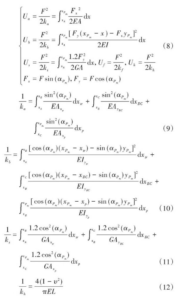
Taking the active gear P as an example, according to the theory of variable cross-section elastic cantilever beam and the engagement action point position shown in Figure 3, the analytical calculation visible formulas (8) for the axial compression energy Ua, bending energy Ub, shear energy Us, matrix energy Uf and contact energy Uh of the single gear teeth caused by contact load are given.From this, the corresponding axial compressive stiffness ka, bending stiffness kb, shear stiffness KS and contact stiffness KH (shown in Formula (9) – 12) can be derived, while the base stiffness KF is calculated by the analytical method proposed in reference [20] (shown in Formula (13).
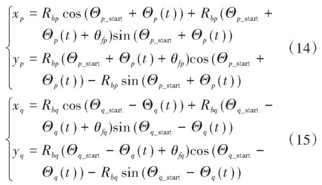
In Formula (9) – 11, there are two variables, XTR and YTR are independent variables as functions of gamma, as shown in Formula (7).Assuming that the pinion P starts at the starting point of rodent B2 and the rotation angle P (t) is a function of time, then the variables XP and YP can be expressed by the rotation angle function P (t), as shown in equation (14).Similarly, expressions for the rotation angle function q(t) of the driven gear variables XQ and YQ are obtained as shown in formula (15).
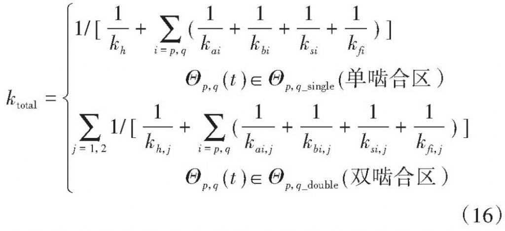
According to Figure 1(b), the gear teeth will have double-single-double alternating engagement in the actual engagement action line B1B2, and the range of values for p(t) and q(t) of double-pair and single-pair gear engagement in formula (6) is deduced to derive the comprehensive TVMS of spur gear pair, as shown in formula (16).