
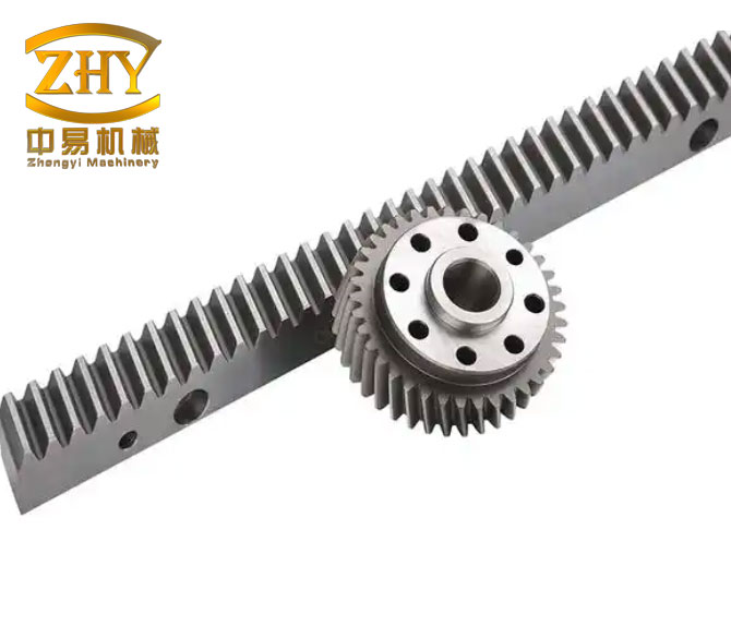
As a mechanical engineer who has spent many years designing transmission systems for mining machinery, engineering machinery, offshore equipment, and metallurgical plants, I have repeatedly seen how critical rack and pinion gears are in heavy-duty applications. These systems are simple in structure and direct in power transmission, which is why they appear in jack-up drilling platforms, large excavators, mine hoists, and other equipment that must operate under extreme loads. In my experience, the most dangerous failure mode for heavy-duty rack and pinion gears is tooth breakage. A single broken tooth can stop an entire machine, cause secondary damage, and create unacceptable economic loss. Therefore, I always place bending strength and root stress control at the center of the design process.
For heavy-duty rack and pinion gears, the common practice is to use a large module and a small number of teeth on the pinion. For example, in climbing mechanisms of jack-up drilling platforms, I have used pinions with as few as seven teeth and modules of 80 mm or 100 mm. For the crowd drive of large excavators, I typically use fourteen teeth and modules of 40 mm or 50 mm. Unfortunately, there is no mature standard or commercial software that directly covers such large-module rack and pinion gears. The usual approach is to build a finite element model, calculate the root stress, and then redesign the tooth profile if the stress is too high. This iterative process is slow and inefficient, especially when I need to explore many initial design options. For this reason, I have developed a fast analytical method that links tooth profile parameters, load distribution, and root stress for heavy-duty rack and pinion gears.
Tooth profile design for heavy-duty rack and pinion gears. Large-module rack and pinion gears are not suitable for ordinary hobbing or shaping. In many cases, the pinion is milled according to a special tooth profile, while the rack is cut by numerical control or produced by casting. On large mining excavators, I have seen approximate involute profiles made of three circular arcs: a root arc below the base circle, an arc between the root arc and the pitch circle, and another arc above the pitch circle. Such approximations often produce large transmission errors, vibration, and severe wear. If the root arc is poorly chosen, tooth breakage can occur. The key to solving these problems is not a single parameter but the matching of several parameters: tip thickness, contact ratio, backlash, root fillet radius, and rack tooth height.
Tooth tip thickness. I begin with the tooth tip because it controls wear and plastic deformation in open rack and pinion gears. For open gears under fatigue loading, I recommend a tip thickness of at least \(0.4m\). For static loading, such as in jack-up drilling platform climbing systems, a tip thickness of at least \(0.15m\) is often sufficient. In some imported climbing pinions used in 300 ft and 400 ft jack-up units, the tip thickness has been about \(0.14m\) to \(0.15m\). In large excavator crowd drives, I have observed values around \(0.41m\) and \(0.42m\). The tip thickness is calculated from the following relationships:
$$S_a = d_a \left( \frac{\pi Z}{2} + \operatorname{inv}\alpha – \operatorname{inv}\alpha_a \right)$$
$$\cos\alpha_a = \frac{d_b}{d_a}$$
Here, \(S_a\) is the tooth tip thickness, \(d_a\) is the tip circle diameter, \(Z\) is the number of teeth, \(\alpha\) is the reference pressure angle, \(\alpha_a\) is the pressure angle at the tip circle, and \(d_b\) is the base circle diameter. The involute function is \(\operatorname{inv}\alpha = \tan\alpha – \alpha\). I use these equations to check whether the chosen addendum and profile shift produce a tip that is thick enough for the expected wear life of the rack and pinion gears.
Contact ratio. The contact ratio is another decisive parameter. For fatigue-loaded rack and pinion gears, I recommend a contact ratio \(\epsilon \ge 1.2\). A smaller contact ratio increases impact at engagement and reduces bending strength. For mainly static loading, such as jack-up platform drives, \(\epsilon \ge 1.05\) can be acceptable. Static-loaded rack and pinion gears often use pressure angles greater than \(25^\circ\), which increases the contact ratio and can make the tip nearly pointed. The contact ratio is calculated as:
$$\epsilon = \frac{Z_1(\tan\alpha_{a1} – \tan\alpha)}{2\pi} + \frac{2h’_{a2}}{\pi m \sin 2\alpha}$$
In this expression, \(Z_1\) is the number of pinion teeth, \(\alpha_{a1}\) is the pinion tip pressure angle, \(h’_{a2}\) is the effective addendum of the rack above the meshing point, and \(m\) is the module. I use this equation together with the tip thickness equation to select the tip circle diameter and the profile shift. If I choose a short tooth with a large negative profile shift, the pinion tooth thickness increases, but the rack tooth thickness at the meshing point decreases. This can increase pinion strength but weaken the rack. Therefore, I follow the principle of equal strength between the pinion and the rack when selecting the profile shift. In most heavy-duty rack and pinion gears, I apply a positive profile shift to the pinion.
Backlash. Backlash must be provided to accommodate manufacturing errors, center distance variation, cumulative pitch error, and thermal expansion caused by friction. For open rack and pinion gears, I usually take the circumferential backlash as \(0.12m\) to \(0.15m\). I obtain this backlash by thinning both the pinion and the rack teeth. The rack root thickness remains larger than the pinion root thickness, which is consistent with the fact that the rack experiences fewer load cycles in many applications.
Root fillet radius. After the previous parameters are fixed, I determine the root fillet radius. For the pinion, I prefer a single circular arc because it reduces root stress more effectively than a double arc. However, a large root fillet can cause meshing interference. The solution is to keep the effective involute long enough and then enlarge the root fillet as much as possible. The root fillet radius is controlled by the lowest meshing point. For heavy-duty rack and pinion gears, this point is usually on or slightly above the base circle, typically 2 mm to 3 mm above it. I set the tangent point between the root arc and the involute at this lowest meshing point. The fillet radius is then:
$$r_\rho = \frac{D_b}{2} \left[ \tan\left(\alpha_{ce} + \operatorname{inv}\alpha_{ce} + \frac{\pi}{Z} – \frac{S_{\min}}{D} – \operatorname{inv}\alpha \right) – \tan\alpha_{ce} \right]$$
$$\alpha_{ce} = \arccos\left(\frac{D_b}{D_{ce}}\right)$$
Here, \(r_\rho\) is the root fillet radius, \(D_b\) is the base circle diameter, \(\alpha_{ce}\) is the pressure angle at the tangent point, \(S_{\min}\) is the actual reference circle tooth thickness, \(D\) is the reference circle diameter, and \(D_{ce}\) is the diameter at the tangent point. I use \(D_{ce} = D_b + 2\) to \(3\) mm. This method gives me a fillet that is large enough to lower root stress without interfering with the mating rack. For the rack, I may use a double circular arc to reduce the rack root height, increase the rack body thickness, and limit deformation. The rack root stress is usually less critical than the pinion root stress in heavy-duty rack and pinion gears, but I still verify it.
Rack tooth profile. For rack and pinion gears, the pitch point always lies on the pinion reference circle regardless of whether the mounting distance is standard. I calculate the effective addendum of the rack above the meshing point using the following equations:
$$h’_{a2} = r – r_{ce}\cos(\alpha – \alpha_{ce})$$
$$h_{a2e} = h’_{a2} + Xm$$
$$h_{a2} = h_{f1} – C_m^*$$
In these equations, \(h’_{a2}\) is the rack tooth height above the meshing point, \(r\) is the pinion reference radius, \(r_{ce}\) is the radius at the tangent point between the root arc and the involute, \(X\) is the profile shift coefficient, \(h_{a2e}\) is the effective rack addendum, \(h_{a2}\) is the total rack tooth height, \(h_{f1}\) is the pinion root depth, and \(C_m^*\) is the tip clearance. For open rack and pinion gears, I usually take the tip clearance as 10 mm to 12 mm so that sufficient lubricant can be stored on the tooth flanks. This clearance is especially important in dusty and high-load environments where oil film renewal is difficult.
Root bending strength of rack and pinion gears. Many methods exist for calculating the root bending stress of large-module rack and pinion gears. Some researchers use integration methods, and others use mapping functions. The folded-section method is more accurate than the flat-section method, but it is complex. The ISO 30° tangent method defines a flat critical section and is simpler. Test results show that the difference between the folded-section and flat-section results is usually within 5% to 6%. For low-speed, heavy-duty rack and pinion gears, manufacturing accuracy is often low, and no specialized software is available. Most designers use finite element analysis, but that requires modeling and is not convenient for initial parameter studies. I therefore use a fast analytical method based on the ISO 30° tangent line. The key question is whether the root stress should be calculated at the single-tooth contact point or at the tooth tip. This depends on the load distribution coefficient \(K_a\).
$$K_a = \frac{\epsilon}{2} \left( 0.9 + \frac{0.4 C_r \Delta}{F_{teff}/b} \right)$$
In this formula, \(C_r\) is the average mesh stiffness of two pairs of teeth in contact, \(\Delta\) is the base pitch difference, \(\epsilon\) is the contact ratio, \(F_{teff}\) is the effective circumferential force on the reference circle, and \(b\) is the face width. The effective force is \(F_{teff} = F_t K_A K_v K_B\), where \(F_t\) is the nominal tangential force, \(K_A\) is the application factor, \(K_v\) is the dynamic factor, and \(K_B\) is the load distribution factor. When \(K_a \le 1\), the maximum stress occurs at the single-tooth contact point. When \(K_a \ge 1\), the entire load is assumed to act at the tooth tip, and the root stress must be calculated at the tip loading position. In low-speed, heavy-duty rack and pinion gears, manufacturing accuracy is usually lower than grade 11. Even if the theoretical contact ratio is greater than 1.2, the load is often carried by a single tooth during transmission. Therefore, I calculate the root stress under tooth-tip loading rather than single-tooth contact loading for these rack and pinion gears.
ISO 30° tangent method for root stress. The root stress formula is:
$$\sigma_{F0} = \frac{F_n \cos\delta_a}{b m} Y_{Fa} Y_{Sa}$$
$$Y_{Fa} = \frac{6(h_F/m)\cos\delta_a}{(S_F/m)^2 \csc\alpha}$$
$$Y_{Sa} = (1.2 + 0.13 L_a) q_s \frac{1}{1.21 + 2.3/L_a}$$
Here, \(\sigma_{F0}\) is the nominal root stress, \(F_n\) is the normal load at the effective tip, \(\delta_a\) is the load angle, \(b\) is the face width, \(m\) is the module, \(Y_{Fa}\) is the form factor, \(Y_{Sa}\) is the stress correction factor, \(S_F\) is the critical section thickness, \(h_F\) is the bending moment arm, \(L_a\) is the load application distance, and \(q_s\) is the notch parameter. The critical section thickness and the bending moment arm are the two most important geometric quantities. I derive them separately for the pinion and the rack.
Pinion critical section. Using the geometry of the 30° tangent line, the critical section thickness and the bending moment arm for the pinion are:
$$S_F = 2(r_f + r_\rho)\sin\frac{\pi}{Z} – 2r_\rho \cos 30^\circ$$
$$h_F = \frac{r_b}{\cos\delta_a} – (r_f + r_\rho)\cos\frac{\pi}{Z} + r_\rho \sin 30^\circ$$
In these equations, \(r_f\) is the root circle radius, \(r_\rho\) is the root fillet radius, \(Z\) is the number of pinion teeth, \(r_b\) is the base circle radius, and \(\delta_a\) is the load angle. I use these expressions for the pinion of heavy-duty rack and pinion gears because the pinion usually has fewer teeth and therefore a higher root stress.
Rack critical section. For the rack, the critical section thickness and the bending moment arm are:
$$S_F = \pi m – 2r_\rho \cos 30^\circ – e$$
$$h_F = h – \frac{S_a}{2}\tan\alpha – r_\rho(1 – \sin 30^\circ)$$
Here, \(e\) is the distance between the centers of two adjacent root arcs; for a single circular arc, \(e = 0\). \(h\) is the effective rack height, \(S_a\) is the tooth thickness at the effective rack height, and \(\alpha\) is the pressure angle. For the rack in rack and pinion gears, the load angle at any point is equal to the pressure angle because the rack flank is straight. This simplifies the calculation considerably.
Load angle calculation. The load angle for the pinion is obtained from the following relationships:
$$\delta_a = \psi – \theta – \operatorname{inv}\alpha$$
$$\theta = \frac{1}{Z}\left(\frac{\pi}{2} + 2X\tan\alpha\right)$$
$$\psi = \sqrt{\left(\frac{r_a}{r_b}\right)^2 – 1}$$
$$\delta_a = \sqrt{\left(\frac{r_a}{r_b}\right)^2 – 1} – \frac{1}{Z}\left(\frac{\pi}{2} + 2X\tan\alpha\right) – \operatorname{inv}\alpha$$
In these equations, \(r_a\) is the tip circle radius, \(r_b\) is the base circle radius, \(Z\) is the number of teeth, \(X\) is the profile shift coefficient, and \(\alpha\) is the reference pressure angle. The load angle is essential for calculating both the form factor and the bending moment arm. I always check the load angle for the worst loading position, which is the tooth tip for low-accuracy rack and pinion gears.
Worked example for a jack-up drilling platform. To demonstrate the method, I use a climbing pinion and rack from a 300 ft jack-up drilling platform. The normal module is \(m = 80\) mm, the number of pinion teeth is \(Z = 7\), the reference diameter is \(d = 560\) mm, the normal profile shift coefficient is \(X = 0.28\), and the pressure angle is \(\alpha = 30^\circ\). The pinion face width is 190 mm, the rack face width is 177 mm, and the jacking force is 2000 kN. I calculate the tooth profile using the equations above. The resulting root fillet radius is 35 mm, and the tooth tip thickness is \(0.15m\). The geometric parameters are summarized in Table 1.
| Parameter | Symbol | Value | Unit |
|---|---|---|---|
| Normal module | \(m\) | 80 | mm |
| Number of pinion teeth | \(Z\) | 7 | – |
| Reference diameter | \(d\) | 560 | mm |
| Normal profile shift coefficient | \(X\) | 0.28 | – |
| Pressure angle | \(\alpha\) | 30 | ° |
| Pinion face width | \(b\) | 190 | mm |
| Rack face width | \(b_{\text{rack}}\) | 177 | mm |
| Jacking force | \(F\) | 2000 | kN |
| Tip thickness | \(S_a\) | 0.15\(m\) | mm |
| Root fillet radius | \(r_\rho\) | 35 | mm |
For this example, I also build a finite element model with one pair of teeth in contact. The jacking force is applied to the rack, and I calculate the root stress for both the engaging and disengaging states. The analytical and finite element results are compared in Table 2. The maximum difference is about 5.1%, which confirms that my analytical method is sufficiently accurate for initial design of heavy-duty rack and pinion gears.
| Item | Analytical result (MPa) | Finite element result (MPa) | Error (%) |
|---|---|---|---|
| Pinion root | 514 | 501 | 2.5 |
| Rack root | 574 | 546 | 5.1 |
The results show that the pinion root stress is lower than the rack root stress in this particular case, but both are below the yield strength of the selected material. Because the jack-up drilling platform climbing system mainly carries static loads, I compare the root stress directly with the material yield strength rather than using a fatigue limit. For fatigue-loaded rack and pinion gears, I would instead compare the calculated stress with the allowable bending fatigue stress and apply the appropriate safety factor.
Design criteria and parameter selection. Based on my experience with heavy-duty rack and pinion gears, I have summarized the recommended design criteria in Table 3. These criteria are not arbitrary; they come from balancing tooth tip wear, contact impact, backlash storage, and root fillet size. For fatigue-loaded open gears, the tip thickness must be large enough to resist wear, and the contact ratio must be high enough to reduce impact. For static-loaded rack and pinion gears, the tip can be thinner, but the pressure angle is usually larger, which naturally increases the contact ratio and can cause a pointed tip if the addendum is too large.
| Parameter | Fatigue-loaded rack and pinion gears | Static-loaded rack and pinion gears |
|---|---|---|
| Tip thickness \(S_a\) | \(\ge 0.4m\) | \(\ge 0.15m\) |
| Contact ratio \(\epsilon\) | \(\ge 1.2\) | \(\ge 1.05\) |
| Circumferential backlash | \(0.12m\) to \(0.15m\) | \(0.12m\) to \(0.15m\) |
| Pinion root fillet | Single circular arc | Single circular arc |
| Rack root fillet | Double circular arc if needed | Double circular arc if needed |
| Profile shift | Positive on pinion | Positive on pinion |
Load distribution coefficient and its meaning. The load distribution coefficient \(K_a\) tells me whether the maximum root stress should be evaluated at the single-tooth contact point or at the tooth tip. In low-speed, heavy-duty rack and pinion gears, the manufacturing accuracy is often not high enough to guarantee smooth load sharing between adjacent teeth. Even when the theoretical contact ratio is greater than 1.2, the actual contact may be concentrated on one tooth. Therefore, \(K_a\) is often greater than 1, and I must calculate the root stress at the tooth tip. Table 4 summarizes this decision rule.
| Condition | Interpretation for rack and pinion gears |
|---|---|
| \(K_a \le 1\) | The maximum root stress occurs at the single-tooth contact point. |
| \(K_a \ge 1\) | The full load acts at the tooth tip, and the root stress is calculated at the tip loading position. |
Critical section formulas for pinion and rack. Table 5 collects the critical section formulas that I use for heavy-duty rack and pinion gears. These formulas are derived from the ISO 30° tangent construction and are valid for both the pinion and the rack after substituting the appropriate geometric parameters. The pinion formula uses the root circle radius \(r_f\), the fillet radius \(r_\rho\), and the number of teeth \(Z\). The rack formula uses the module \(m\), the fillet radius \(r_\rho\), the distance between root arc centers \(e\), the effective rack height \(h\), the tooth thickness \(S_a\), and the pressure angle \(\alpha\).
| Component | Critical section thickness \(S_F\) | Bending moment arm \(h_F\) |
|---|---|---|
| Pinion | \(2(r_f + r_\rho)\sin\frac{\pi}{Z} – 2r_\rho \cos 30^\circ\) | \(\frac{r_b}{\cos\delta_a} – (r_f + r_\rho)\cos\frac{\pi}{Z} + r_\rho \sin 30^\circ\) |
| Rack | \(\pi m – 2r_\rho \cos 30^\circ – e\) | \(h – \frac{S_a}{2}\tan\alpha – r_\rho(1 – \sin 30^\circ)\) |
Influence of tooth profile parameters on root stress and wear. I have studied how each parameter affects the performance of rack and pinion gears. Increasing the root fillet radius reduces the stress concentration and lowers the root stress, but it also reduces the effective involute length and can cause interference. Increasing the profile shift on the pinion increases the pinion tooth thickness and root thickness, which lowers the pinion root stress. However, the same positive shift reduces the rack tooth thickness at the meshing point, which can increase the rack root stress and wear. Increasing the pressure angle increases the contact ratio and the tooth root thickness, but it also increases the radial force and can make the tip thinner. Increasing the module increases the tooth size and the root thickness, which lowers the root stress for a given load, but it also increases the size and weight of the rack and pinion gears. I always try to find a balanced design rather than optimizing a single parameter.
Comparison with finite element analysis. The finite element model I use for verification is relatively simple. I take one pair of teeth in contact, apply the jacking force to the rack, and constrain the pinion. I calculate the root stress for both the engaging and disengaging positions. The analytical method gives a pinion root stress of 514 MPa, while the finite element result is 501 MPa, a difference of 2.5%. For the rack, the analytical result is 574 MPa, and the finite element result is 546 MPa, a difference of 5.1%. These differences are acceptable for initial design because the analytical method is much faster and allows me to explore many design variants before committing to a detailed finite element analysis. For final verification, I still recommend a finite element check, especially when the rack and pinion gears operate under variable loads or when the material behavior is nonlinear.
Practical recommendations for heavy-duty rack and pinion gears. Based on my design experience, I recommend the following steps for heavy-duty rack and pinion gears. First, select the module and number of teeth based on the required load capacity and the available space. Second, choose the pressure angle and profile shift to satisfy the equal strength principle between the pinion and the rack. Third, calculate the tip thickness and contact ratio using the equations in this article. Fourth, determine the backlash and root fillet radius. Fifth, calculate the load distribution coefficient to decide whether the root stress should be evaluated at the single-tooth contact point or at the tooth tip. Sixth, use the ISO 30° tangent method to calculate the root stress for both the pinion and the rack. Seventh, verify the design with a finite element analysis if the application is critical or if the loads are complex. This workflow has helped me reduce design iterations and avoid the costly trial-and-error approach that was once common for large-module rack and pinion gears.
Material and heat treatment considerations. The root stress calculation is only useful if the material and heat treatment are selected correctly. For heavy-duty rack and pinion gears, I usually specify a high-strength alloy steel with sufficient hardenability. The pinion is often carburized or nitrided to increase surface hardness and wear resistance, while the rack may be through-hardened or surface-hardened depending on the manufacturing method. The root stress must be compared with the allowable bending stress, which depends on the core hardness, the fillet surface condition, and the stress concentration. In static-loaded rack and pinion gears, the yield strength is the primary criterion. In fatigue-loaded rack and pinion gears, the bending fatigue limit and the safety factor are the primary criteria. I always account for the size effect, the surface finish, and the notch sensitivity when selecting the allowable stress.
Lubrication and maintenance. Open rack and pinion gears require reliable lubrication because the tooth flanks are exposed to dust, water, and debris. The tip clearance of 10 mm to 12 mm that I use for heavy-duty rack and pinion gears provides space for lubricant storage. I recommend a high-viscosity adhesive lubricant that can stay on the tooth flanks under high contact pressure. Regular inspection of the root fillet and the tooth tip is essential because wear and crack initiation often begin at these locations. If the root fillet is too small, a fatigue crack can initiate and propagate, leading to tooth breakage. If the tip is too thin, plastic deformation and wear can change the tooth profile and increase dynamic loads. Both failure modes can be avoided by following the design and calculation methods described in this article.
Limitations of the analytical method. The analytical method I present here is intended for low-speed, heavy-duty rack and pinion gears with large modules. It assumes that the load is applied either at the single-tooth contact point or at the tooth tip, depending on the load distribution coefficient. It also assumes that the critical section can be approximated by the ISO 30° tangent line. For very high-speed rack and pinion gears, dynamic effects and thermal effects may require a more detailed analysis. For very large modules, the size effect and the casting or forging defects may also influence the root stress. In such cases, I use the analytical method for initial design and then perform a finite element analysis with realistic boundary conditions and material properties.
Summary of equations. For convenience, Table 6 collects the main equations used in this article. These equations cover tooth tip thickness, contact ratio, root fillet radius, rack effective addendum, load distribution coefficient, root stress, critical section thickness, bending moment arm, and load angle. I use these equations together as a complete design and calculation procedure for heavy-duty rack and pinion gears.
| Quantity | Equation |
|---|---|
| Tip thickness | \(S_a = d_a \left( \frac{\pi Z}{2} + \operatorname{inv}\alpha – \operatorname{inv}\alpha_a \right)\) |
| Tip pressure angle | \(\cos\alpha_a = \frac{d_b}{d_a}\) |
| Contact ratio | \(\epsilon = \frac{Z_1(\tan\alpha_{a1} – \tan\alpha)}{2\pi} + \frac{2h’_{a2}}{\pi m \sin 2\alpha}\) |
| Root fillet radius | \(r_\rho = \frac{D_b}{2} \left[ \tan\left(\alpha_{ce} + \operatorname{inv}\alpha_{ce} + \frac{\pi}{Z} – \frac{S_{\min}}{D} – \operatorname{inv}\alpha \right) – \tan\alpha_{ce} \right]\) |
| Fillet tangent pressure angle | \(\alpha_{ce} = \arccos\left(\frac{D_b}{D_{ce}}\right)\) |
| Rack effective addendum | \(h’_{a2} = r – r_{ce}\cos(\alpha – \alpha_{ce})\) |
| Rack effective tooth height | \(h_{a2e} = h’_{a2} + Xm\) |
| Rack total tooth height | \(h_{a2} = h_{f1} – C_m^*\) |
| Load distribution coefficient | \(K_a = \frac{\epsilon}{2} \left( 0.9 + \frac{0.4 C_r \Delta}{F_{teff}/b} \right)\) |
| Root stress | \(\sigma_{F0} = \frac{F_n \cos\delta_a}{b m} Y_{Fa} Y_{Sa}\) |
| Form factor | \(Y_{Fa} = \frac{6(h_F/m)\cos\delta_a}{(S_F/m)^2 \csc\alpha}\) |
| Stress correction factor | \(Y_{Sa} = (1.2 + 0.13 L_a) q_s \frac{1}{1.21 + 2.3/L_a}\) |
| Pinion critical section | \(S_F = 2(r_f + r_\rho)\sin\frac{\pi}{Z} – 2r_\rho \cos 30^\circ\) |
| Pinion bending moment arm | \(h_F = \frac{r_b}{\cos\delta_a} – (r_f + r_\rho)\cos\frac{\pi}{Z} + r_\rho \sin 30^\circ\) |
| Rack critical section | \(S_F = \pi m – 2r_\rho \cos 30^\circ – e\) |
| Rack bending moment arm | \(h_F = h – \frac{S_a}{2}\tan\alpha – r_\rho(1 – \sin 30^\circ)\) |
| Load angle | \(\delta_a = \psi – \theta – \operatorname{inv}\alpha\) |
| Auxiliary angle \(\theta\) | \(\theta = \frac{1}{Z}\left(\frac{\pi}{2} + 2X\tan\alpha\right)\) |
| Auxiliary angle \(\psi\) | \(\psi = \sqrt{\left(\frac{r_a}{r_b}\right)^2 – 1}\) |
| Explicit load angle | \(\delta_a = \sqrt{\left(\frac{r_a}{r_b}\right)^2 – 1} – \frac{1}{Z}\left(\frac{\pi}{2} + 2X\tan\alpha\right) – \operatorname{inv}\alpha\) |
Final remarks. The design of heavy-duty rack and pinion gears requires careful attention to tooth profile, root fillet, load distribution, and root stress. The analytical method I have described allows me to calculate the root stress quickly and accurately enough for initial design. The comparison with finite element analysis shows that the maximum error is about 5.1%, which is acceptable for this stage of design. By using the recommended design criteria and the equations in this article, I can avoid the common failure modes of tooth breakage and excessive wear in large-module rack and pinion gears. I can also reduce the number of design iterations and shorten the development cycle for heavy machinery that uses rack and pinion gears. In my future work, I plan to extend this method to include dynamic load effects and to validate it with more field data from different types of rack and pinion gears.