
I treat the duplex helical method as a manufacturing process for a spiral bevel gear pair in which the tooth surface is generated by a cutter and a rolling cradle whose motions are coupled through a first-order helical relation. In my analysis, the central question is not merely whether a spiral bevel gear can be cut to nominal geometry, but how small errors in the cutting parameters propagate into the meshing behavior of the spiral bevel gear pair. Because the duplex helical method differs from the conventional five-cut method in both the generating motion and the correction strategy, I cannot simply inherit every empirical rule from five-cut practice. I therefore build a tooth contact analysis framework in which the gear is generated by a formate process and the pinion is generated by a duplex helical process, and I then perturb the pinion cutting parameters one at a time. The meshing metrics I monitor are the contact trace position, the transmission error curve, and the instantaneous contact ellipse, especially its semi-major axis. These quantities determine whether a spiral bevel gear pair will run quietly, whether it will concentrate load near a tooth edge, and whether the contact pattern will remain stable under small manufacturing variations.
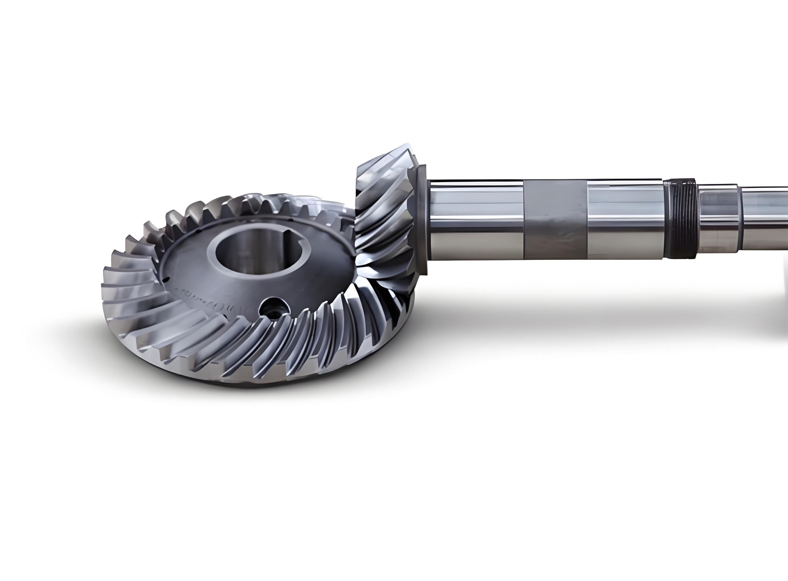
For a spiral bevel gear, the contact trace is not a decorative feature. It is the geometric signature of the relative motion between the two tooth surfaces. A contact trace that is too short reduces overlap and may increase noise; a contact trace that is too long can promote diagonal contact and edge loading. The transmission error curve of a spiral bevel gear describes the departure of the output rotation from a perfectly uniform ratio. A well-behaved transmission error curve should be continuous, should open downward in the usual plotting convention, and should be reasonably symmetric about the mean position. The instantaneous contact ellipse is the local footprint of the meshing tooth pair. When the semi-major axes of the successive ellipses vary excessively, the contact pattern becomes diamond-shaped, hourglass-shaped, or otherwise irregular. For a spiral bevel gear under load, these irregularities can become stress concentrations and can accelerate pitting or scoring.
I define the theoretical tooth surfaces of the spiral bevel gear pair in a machine coordinate system. The pinion surface is written as a function of the cutter parameter, the cutter phase angle, and the cradle rotation:
$$ \mathbf{r}_{1} = \mathbf{r}_{1}(u_{1},\theta_{1},\phi_{1}) $$
where \(u_{1}\) is the distance along the cutting edge from a reference point, \(\theta_{1}\) is the cutter phase angle, and \(\phi_{1}\) is the cradle rotation angle for the pinion. The gear surface, generated by the formate method, is written as:
$$ \mathbf{r}_{2} = \mathbf{r}_{2}(u_{2},\theta_{2}) $$
where \(u_{2}\) and \(\theta_{2}\) are the corresponding cutter parameters for the gear. The unit normal of each surface follows from the cross product of the partial derivatives. For the pinion, I use:
$$ \mathbf{n}_{1} = \frac{\partial \mathbf{r}_{1}}{\partial u_{1}} \times \frac{\partial \mathbf{r}_{1}}{\partial \theta_{1}} $$
and for the gear:
$$ \mathbf{n}_{2} = \frac{\partial \mathbf{r}_{2}}{\partial u_{2}} \times \frac{\partial \mathbf{r}_{2}}{\partial \theta_{2}} $$
The meshing equation for the pinion generation is expressed through the relative velocity between the cutter and the workpiece:
$$ f_{1}(u_{1},\theta_{1},\phi_{1}) = \mathbf{n}_{1} \cdot \mathbf{v}_{1}^{(12)} = 0 $$
and for the gear:
$$ f_{2}(u_{2},\theta_{2}) = \mathbf{n}_{2} \cdot \mathbf{v}_{2}^{(12)} = 0 $$
In the tooth contact analysis of the assembled spiral bevel gear pair, I transform the pinion and gear surfaces into a common fixed frame. The contact point must satisfy both positional continuity and normal coplanarity:
$$ \mathbf{r}_{1}^{(f)} – \mathbf{r}_{2}^{(f)} = \mathbf{0} $$
$$ \mathbf{n}_{1}^{(f)} \times \mathbf{n}_{2}^{(f)} = \mathbf{0} $$
I solve this system for the unknown surface parameters and the input rotation angle. Once the solution is obtained, I compute the transmission error of the spiral bevel gear pair as:
$$ \Delta\phi_{2}(\phi_{1}) = \left[\phi_{2}(\phi_{1}) – \phi_{2}^{0}\right] – \frac{N_{1}}{N_{2}}\left[\phi_{1} – \phi_{1}^{0}\right] $$
where \(N_{1}\) and \(N_{2}\) are the tooth numbers of the pinion and gear, and the superscript \(0\) denotes the reference position. The instantaneous contact ellipse is obtained from the second-order local geometry. If the local coordinates on the tangent plane are \(x\) and \(y\), the contact ellipse can be written in quadratic form:
$$ A x^{2} + Bxy + C y^{2} + D x + E y + F = 0 $$
The semi-major axis \(a\) and semi-minor axis \(b\) of the instantaneous contact ellipse are determined from the eigenvalues of the local curvature difference matrix. I focus on \(a\), because its variation along the contact trace strongly affects the visual contact pattern of the spiral bevel gear.
Cutting Parameter Error Model
For the duplex helical method, the pinion cutting parameters form a vector. I collect them as:
$$ \boldsymbol{\lambda}_{1} = \left[ r_{01}, \alpha_{1}, S_{1}, I_{1}, J_{1}, E_{1}, \delta_{M1}, X_{1}, X_{B1}, i_{01}, q_{1}, H_{l1} \right]^{T} $$
Here \(r_{01}\) is the cutter radius, \(\alpha_{1}\) is the blade profile angle, \(S_{1}\) is the radial cutter position, \(I_{1}\) is the cutter tilt angle, \(J_{1}\) is the cutter swing angle, \(E_{1}\) is the vertical offset, \(\delta_{M1}\) is the machine root angle, \(X_{1}\) is the axial setting, \(X_{B1}\) is the sliding base, \(i_{01}\) is the ratio of roll, \(q_{1}\) is the angular cutter position, and \(H_{l1}\) is the first-order helical motion coefficient. I introduce an error vector:
$$ \Delta\boldsymbol{\lambda}_{1} = \left[ \Delta r_{01}, \Delta\alpha_{1}, \Delta S_{1}, \Delta I_{1}, \Delta J_{1}, \Delta E_{1}, \Delta\delta_{M1}, \Delta X_{1}, \Delta X_{B1}, \Delta i_{01}, \Delta q_{1}, \Delta H_{l1} \right]^{T} $$
The actual cutting parameters become:
$$ \boldsymbol{\lambda}_{1}’ = \boldsymbol{\lambda}_{1} + \Delta\boldsymbol{\lambda}_{1} $$
Substituting this vector into the pinion tooth surface equation gives the perturbed pinion surface:
$$ \mathbf{r}_{1e} = \mathbf{r}_{1}\left(u_{1},\theta_{1},\phi_{1},\boldsymbol{\lambda}_{1} + \Delta\boldsymbol{\lambda}_{1}\right) $$
I then perform tooth contact analysis between the perturbed pinion surface and the nominal gear surface. The contact pattern displacement is defined as:
$$ \Delta X = f_{1}\left(u_{1},\phi_{1},\theta_{1},u_{2},\theta_{2},\boldsymbol{\lambda}_{1}’\right) $$
$$ \Delta Y = f_{2}\left(u_{1},\phi_{1},\theta_{1},u_{2},\theta_{2},\boldsymbol{\lambda}_{1}’\right) $$
where \(\Delta X\) is the displacement of the contact pattern center in the tooth length direction and \(\Delta Y\) is the displacement in the tooth height direction. I also define a local sensitivity coefficient:
$$ S_{\lambda}^{X} = \frac{\partial (\Delta X)}{\partial (\Delta \lambda)} $$
$$ S_{\lambda}^{Y} = \frac{\partial (\Delta Y)}{\partial (\Delta \lambda)} $$
These coefficients are not constant over the whole tooth surface, but they provide a compact way to compare the influence of different cutting parameters on the spiral bevel gear meshing behavior.
Example Spiral Bevel Gear Pair
I use a hypoid spiral bevel gear pair with an \(8 \times 43\) tooth combination as my numerical example. The gear pair has a left-hand pinion and a right-hand gear, with a shaft angle of \(90^{\circ}\). The basic geometric parameters are listed in Table 1. These values define the blank geometry and the mounting position of the spiral bevel gear pair.
| Parameter | Pinion | Gear |
|---|---|---|
| Number of teeth | 8 | 43 |
| Large-end module (mm) | — | 6.8610 |
| Face width (mm) | 43.7617 | 40.0000 |
| Pinion offset (mm) | 25.4000 | — |
| Shaft angle (deg) | 90 | 90 |
| Hand of spiral | Left | Right |
| Outer cone distance (mm) | 150.5594 | 151.2696 |
| Pitch cone angle (deg) | 12.5500 | 77.2000 |
| Mid-point spiral angle (deg) | 45.0000 | 33.8167 |
| Large-end addendum (mm) | 9.1436 | 1.7926 |
| Large-end dedendum (mm) | 3.1182 | 10.4692 |
The cutting parameters for the duplex helical method are given in Table 2. The pinion is cut with a tilted cutter and a non-zero first-order helical motion coefficient, while the gear is generated by the formate method. The angular cutter position, radial cutter position, and ratio of roll are all active in the pinion generation. I perturb these values individually and observe the resulting changes in the spiral bevel gear contact pattern.
| Parameter | Pinion | Gear |
|---|---|---|
| Cutter radius (mm) | 114.5846 | 114.3000 |
| Inside blade profile angle (deg) | 25.0000 | 30.0000 |
| Outside blade profile angle (deg) | 20.0000 | 15.0000 |
| Point width (mm) | 2.6549 | 3.3000 |
| Radial cutter position (mm) | 116.8173 | 117.9968 |
| Cutter tilt angle (deg) | 16.8362 | 0 |
| Cutter swing angle (deg) | −26.7017 | 0 |
| Vertical offset (mm) | 26.2980 | 0 |
| Machine root angle (deg) | −5.2749 | 68.7300 |
| Axial setting (mm) | 0.0708 | 9.9183 |
| Sliding base (mm) | 14.9710 | 0 |
| Ratio of roll | 5.2722 | 0 |
| Angular cutter position (deg) | 65.4862 | 69.7070 |
| First-order helical motion coefficient (mm/rad) | 5.9269 | 0 |
Meshing Metrics and Their Geometric Meaning
For a spiral bevel gear pair, the tooth contact analysis output is interpreted through several meshing metrics. I summarize them in Table 3. The contact trace describes the path along which the contact point moves from the beginning of mesh to the end of mesh. The transmission error curve describes the angular deviation of the gear from a uniform ratio. The instantaneous contact ellipse describes the local contact footprint. The contact pattern is the envelope of the instantaneous ellipses along the contact trace. In a well-designed spiral bevel gear, the theoretical contact pattern should sit near the middle of the tooth, slightly biased toward the toe or heel depending on the application, and should not run off the edges under light load.
| Metric | Symbol | Geometric meaning | Desired behavior for a spiral bevel gear |
|---|---|---|---|
| Contact trace | \(\Gamma\) | Path of the contact point on the tooth surface | Continuous, not diagonal, no premature edge contact |
| Transmission error | \(\Delta\phi_{2}\) | Deviation from a uniform angular ratio | Continuous, downward-opening, nearly symmetric |
| Instantaneous contact ellipse | \(E_{\mathrm{ins}}\) | Local footprint at one meshing instant | Moderate size, stable orientation |
| Semi-major axis | \(a\) | Long radius of the contact ellipse | Consistent along the contact trace |
| Theoretical contact pattern | \(P_{\mathrm{th}}\) | Envelope of instantaneous ellipses | Centered on the tooth surface |
| Potential contact region | \(P_{\mathrm{pot}}\) | Region that may contact under load | Balanced between top and root |
Sensitivity of Contact Pattern Position
I first examine how the contact pattern center moves when each cutting parameter is perturbed. The displacement in the tooth length direction is \(\Delta X\), and the displacement in the tooth height direction is \(\Delta Y\). The positive and negative perturbations are treated separately because the duplex helical method is nonlinear; a positive error in one parameter does not always produce the mirror image of a negative error.
The ranking of parameter influence is important for practical adjustment of a spiral bevel gear. From my sensitivity study, the ratio of roll has the strongest influence on both \(\Delta X\) and \(\Delta Y\). The blade profile angle has a strong influence on the tooth height direction. The radial cutter position and the machine root angle have a noticeable influence on the tooth length direction. The angular cutter position has almost no influence on the contact pattern center. The remaining parameters produce smaller but still measurable changes. Table 4 gives a qualitative summary.
| Cutting parameter | Influence on \(\Delta X\) | Influence on \(\Delta Y\) | Overall sensitivity rank for spiral bevel gear |
|---|---|---|---|
| Ratio of roll \(\Delta i_{01}\) | Very strong | Very strong | 1 |
| Blade profile angle \(\Delta\alpha_{1}\) | Moderate | Strong | 2 |
| Radial cutter position \(\Delta S_{1}\) | Strong | Moderate | 3 |
| Machine root angle \(\Delta\delta_{M1}\) | Strong | Moderate | 4 |
| Cutter radius \(\Delta r_{01}\) | Moderate | Moderate | 5 |
| First-order helical motion coefficient \(\Delta H_{l1}\) | Moderate | Moderate | 6 |
| Cutter tilt angle \(\Delta I_{1}\) | Small | Small | 7 |
| Cutter swing angle \(\Delta J_{1}\) | Small | Small | 8 |
| Vertical offset \(\Delta E_{1}\) | Small | Small | 9 |
| Axial setting \(\Delta X_{1}\) | Small | Small | 10 |
| Sliding base \(\Delta X_{B1}\) | Small | Small | 11 |
| Angular cutter position \(\Delta q_{1}\) | Almost none | Almost none | 12 |
Effect on Contact Trace and Transmission Error
I now discuss the detailed meshing behavior. The ratio of roll is the most sensitive cutting parameter in the duplex helical method for a spiral bevel gear. A positive ratio-of-roll error moves the convex flank contact trace toward the heel and the top of the tooth. This enlarges the potential contact region near the root. On the concave flank, the same positive error moves the contact trace toward the toe and the root, which enlarges the potential contact region near the top. A negative ratio-of-roll error reverses these tendencies. The transmission error curve also changes. In many cases, the perturbed curve no longer overlaps or intersects the nominal curve, which indicates that edge contact will occur. The parabola opening of the transmission error curve also changes, so the mesh conversion point amplitude changes slightly. This is a critical observation for a spiral bevel gear because a small roll error can alter both the contact position and the dynamic excitation.
The radial cutter position primarily affects the tooth length direction. A positive radial cutter position error moves the convex flank contact trace toward the toe and the root, enlarging the potential contact region near the top. On the concave flank, the contact trace moves toward the heel and the top, enlarging the potential contact region near the root. A negative radial cutter position error reverses the behavior. The transmission error curve again becomes non-overlapping and non-intersecting, so edge contact is likely. The parabola opening changes noticeably, which means the mesh conversion point amplitude changes significantly. For a spiral bevel gear, this means that radial cutter position should not be used as a fine adjustment without checking the transmission error.
The machine root angle affects both flanks in a more symmetric way. A positive machine root angle error moves both the convex and concave contact traces toward the heel and the root. This enlarges the potential contact region near the top. A negative machine root angle error moves both traces toward the toe and the top, enlarging the potential contact region near the root. Because both flanks move in the same direction along the tooth length, the machine root angle is a useful parameter when the entire contact pattern must be shifted along the face width of the spiral bevel gear.
The cutter radius has a smaller but still important effect. A positive cutter radius error moves the convex flank contact trace toward the heel and the top. A negative cutter radius error has the opposite effect. The concave flank is less sensitive to cutter radius. In a spiral bevel gear, this asymmetry means that a cutter radius error can change the balance between the two flanks. If the two flanks are already close to an edge, a cutter radius error may push one flank into an undesirable region while leaving the other flank almost unchanged.
The blade profile angle has a strong influence on the tooth height direction. A positive blade profile angle error moves the convex flank contact trace toward the toe and the top, while the concave flank moves toward the toe and the root. A negative blade profile angle error reverses these directions. The transmission error curve again becomes non-overlapping and non-intersecting, which indicates edge contact. The parabola opening changes substantially, so the mesh conversion point amplitude changes. For a spiral bevel gear, blade profile angle is therefore a primary parameter for adjusting the contact pattern in the tooth height direction, but it must be controlled carefully because of its impact on transmission error.
The first-order helical motion coefficient is unique to the duplex helical method. A positive error moves the convex flank contact trace toward the heel and the top, while the concave flank moves toward the heel and the root. A negative error reverses these tendencies. This parameter changes the coupling between the cradle rotation and the additional helical motion, so it alters the generated spiral bevel gear surface in a way that cannot be reproduced by a simple radial or angular adjustment. I find that the first-order helical motion coefficient is a moderate-sensitivity parameter for contact position, but it can still produce meaningful changes when the design is near a contact boundary.
The angular cutter position has almost no influence on the contact trace position. This is a useful result for a spiral bevel gear manufacturer because it means that angular cutter position can be used for other setup purposes without strongly disturbing the contact pattern. However, it does not mean that angular cutter position has no effect on the tooth surface; it means that the contact pattern center is relatively insensitive to this parameter in the duplex helical method.
Table 5 summarizes the qualitative influence of the main cutting parameters on the convex and concave flanks of the spiral bevel gear. I use the terms toe, heel, top, and root to describe the direction of contact trace movement. The potential contact region is the region that may enter contact under load.
| Parameter and error | Convex flank contact trace | Convex flank potential region | Concave flank contact trace | Concave flank potential region |
|---|---|---|---|---|
| Positive ratio of roll | Heel and top | Root increases | Toe and root | Top increases |
| Negative ratio of roll | Toe and root | Top increases | Heel and top | Root increases |
| Positive radial cutter position | Toe and root | Top increases | Heel and top | Root increases |
| Negative radial cutter position | Heel and top | Root increases | Toe and root | Top increases |
| Positive machine root angle | Heel and root | Top increases | Heel and root | Top increases |
| Negative machine root angle | Toe and top | Root increases | Toe and top | Root increases |
| Positive cutter radius | Heel and top | Root increases | Weak effect | Weak effect |
| Negative cutter radius | Toe and root | Top increases | Weak effect | Weak effect |
| Positive blade profile angle | Toe and top | Root increases | Toe and root | Top increases |
| Negative blade profile angle | Heel and root | Top increases | Heel and top | Root increases |
| Positive first-order helical coefficient | Heel and top | Root increases | Heel and root | Top increases |
| Negative first-order helical coefficient | Toe and root | Top increases | Toe and top | Root increases |
Instantaneous Contact Ellipse Semi-Major Axis
The instantaneous contact ellipse is a local property, but its semi-major axis has a global effect on the contact pattern of the spiral bevel gear. If the semi-major axis is nearly constant along the contact trace, the contact pattern is regular. If it changes rapidly, the pattern becomes irregular. I compute the average semi-major axis for the convex and concave flanks under each perturbation. The nominal values are \(5.3239\,\mathrm{mm}\) for the convex flank and \(5.1054\,\mathrm{mm}\) for the concave flank. Table 6 lists the perturbed values and the deviations from nominal.
| Parameter and error direction | Convex flank average \(a\) (mm) | Convex deviation (mm) | Concave flank average \(a\) (mm) | Concave deviation (mm) |
|---|---|---|---|---|
| Nominal | 5.3239 | — | 5.1054 | — |
| Positive cutter radius \(\Delta r_{01}\) | 5.3590 | +0.0351 | 5.0954 | −0.0100 |
| Negative cutter radius \(\Delta r_{01}\) | 5.3208 | −0.0031 | 5.1220 | +0.0166 |
| Positive blade profile angle \(\Delta\alpha_{1}\) | 5.2931 | −0.0308 | 4.9642 | −0.1412 |
| Negative blade profile angle \(\Delta\alpha_{1}\) | 5.3687 | +0.0448 | 5.1896 | +0.0842 |
| Positive radial cutter position \(\Delta S_{1}\) | 5.4103 | +0.0864 | 5.0263 | −0.0791 |
| Negative radial cutter position \(\Delta S_{1}\) | 5.3120 | −0.0119 | 5.2379 | +0.1325 |
| Positive cutter tilt angle \(\Delta I_{1}\) | 5.3994 | +0.0755 | 5.1876 | +0.0822 |
| Negative cutter tilt angle \(\Delta I_{1}\) | 5.2482 | −0.0757 | 5.0131 | −0.0923 |
| Positive cutter swing angle \(\Delta J_{1}\) | 5.3498 | +0.0259 | 5.1490 | +0.0436 |
| Negative cutter swing angle \(\Delta J_{1}\) | 5.3217 | −0.0022 | 5.0553 | −0.0501 |
| Positive vertical offset \(\Delta E_{1}\) | 5.3105 | +0.0138 | 5.1140 | +0.0086 |
| Negative vertical offset \(\Delta E_{1}\) | 5.3377 | −0.0134 | 5.0974 | −0.0080 |
| Positive machine root angle \(\Delta\delta_{M1}\) | 5.3727 | +0.0488 | 5.0811 | −0.0243 |
| Negative machine root angle \(\Delta\delta_{M1}\) | 5.2894 | −0.0345 | 5.1354 | +0.0300 |
| Positive axial setting \(\Delta X_{1}\) | 5.3634 | +0.0395 | 5.0508 | −0.0546 |
| Negative axial setting \(\Delta X_{1}\) | 5.3315 | +0.0076 | 5.1558 | +0.0504 |
| Positive sliding base \(\Delta X_{B1}\) | 5.3426 | +0.0187 | 5.0417 | −0.0637 |
| Negative sliding base \(\Delta X_{B1}\) | 5.3410 | +0.0171 | 5.1640 | +0.0586 |
| Positive ratio of roll \(\Delta i_{01}\) | 5.3448 | +0.0209 | 5.2034 | +0.0980 |
| Negative ratio of roll \(\Delta i_{01}\) | 5.3578 | +0.0339 | 4.9658 | −0.1396 |
| Positive angular cutter position \(\Delta q_{1}\) | 5.3152 | −0.0087 | 5.0932 | −0.0122 |
| Negative angular cutter position \(\Delta q_{1}\) | 5.3370 | +0.0131 | 5.1239 | +0.0185 |
| Positive first-order helical coefficient \(\Delta H_{l1}\) | 5.3200 | −0.0039 | 5.0063 | −0.0991 |
| Negative first-order helical coefficient \(\Delta H_{l1}\) | 5.3348 | +0.0109 | 5.1937 | +0.0883 |
Several patterns emerge from Table 6. First, the vertical offset and the angular cutter position have very small effects on the instantaneous contact ellipse. This is consistent with their weak influence on the contact pattern position. Second, the blade profile angle, radial cutter position, cutter tilt angle, and ratio of roll have large effects on the semi-major axis. Third, some parameters lengthen the ellipse on one flank while shortening it on the other. These include cutter radius, radial cutter position, machine root angle, axial setting, and sliding base. Other parameters lengthen or shorten both flanks together. These include blade profile angle, cutter tilt angle, cutter swing angle, vertical offset, ratio of roll, angular cutter position, and first-order helical motion coefficient.
The practical meaning for a spiral bevel gear is that the contact pattern can become irregular even when the contact trace position remains acceptable. If the semi-major axis changes significantly from one end of the contact trace to the other, the contact pattern may become diamond-shaped. If one flank has a much larger ellipse than the other, the load sharing between the two flanks may become uneven. Therefore, I recommend that a duplex helical spiral bevel gear design should be evaluated with both contact trace position and ellipse size criteria.
Coupled Interpretation Through Sensitivity Equations
I can express the first-order influence of a cutting parameter error on the contact pattern through a linearized sensitivity model. Let the nominal contact pattern center be \((X_{0},Y_{0})\). For a small error vector \(\Delta\boldsymbol{\lambda}_{1}\), the perturbed center is approximately:
$$ X \approx X_{0} + \sum_{j} \frac{\partial X}{\partial \lambda_{j}} \Delta\lambda_{j} $$
$$ Y \approx Y_{0} + \sum_{j} \frac{\partial Y}{\partial \lambda_{j}} \Delta\lambda_{j} $$
The transmission error can be linearized in a similar way:
$$ \Delta\phi_{2}(\phi_{1}) \approx \Delta\phi_{2,0}(\phi_{1}) + \sum_{j} \frac{\partial \Delta\phi_{2}}{\partial \lambda_{j}} \Delta\lambda_{j} $$
The semi-major axis of the instantaneous contact ellipse can also be expanded:
$$ a \approx a_{0} + \sum_{j} \frac{\partial a}{\partial \lambda_{j}} \Delta\lambda_{j} $$
These equations are useful for a spiral bevel gear correction strategy. If the goal is to move the contact pattern along the tooth length without changing the transmission error too much, I should choose a parameter with a large \(\partial X/\partial \lambda\) and a small \(\partial \Delta\phi_{2}/\partial \lambda\). If the goal is to move the contact pattern along the tooth height, I should choose a parameter with a large \(\partial Y/\partial \lambda\). In the duplex helical method, the radial cutter position and machine root angle are strong candidates for tooth length adjustment, while the blade profile angle is a strong candidate for tooth height adjustment. The ratio of roll is powerful but dangerous because it changes both directions and strongly affects the transmission error.
Design and Manufacturing Implications
My analysis leads to several practical implications for the duplex helical manufacturing of a spiral bevel gear. First, the ratio of roll should be treated as a high-impact parameter. A positive ratio-of-roll error tends to move the contact pattern toward the heel and top on the convex flank and toward the toe and root on the concave flank. This can enlarge the potential contact region near the root on the convex flank and near the top on the concave flank. If the spiral bevel gear is intended to run under heavy load, this shift may cause edge contact and a sharp rise in local stress. Therefore, the ratio of roll should be set and verified with a full tooth contact analysis rather than adjusted by trial and error.
Second, the radial cutter position is a powerful tool for moving the contact pattern along the tooth length. However, it also changes the transmission error curve and can produce non-overlapping behavior. In my numerical example, a positive radial cutter position error moved the convex flank toward the toe and root and the concave flank toward the heel and top. The transmission error curve became non-overlapping and non-intersecting, which suggests that edge contact will occur. Therefore, when I use radial cutter position to correct the contact pattern of a spiral bevel gear, I must simultaneously check the transmission error curve.
Third, the blade profile angle is the most direct parameter for adjusting the contact pattern in the tooth height direction. A positive blade profile angle error moved the convex flank toward the toe and top and the concave flank toward the toe and root. The transmission error curve also changed significantly. This means that blade profile angle should be controlled tightly during cutter manufacturing and resharpening. Even a small blade profile angle error can change the meshing characteristics of the spiral bevel gear.
Fourth, the machine root angle is a useful parameter when both flanks must move in the same direction along the tooth length. A positive machine root angle error moved both flanks toward the heel and root. This is convenient for shifting the entire contact pattern, but it also changes the potential contact region near the top. If the spiral bevel gear is already close to the top edge, a positive machine root angle error may be undesirable.
Fifth, the cutter radius has an asymmetric effect. It affects the convex flank more than the concave flank. This can be used to balance the two flanks, but it can also destroy an otherwise acceptable balance. In a duplex helical process, the cutter radius should be measured carefully and compensated in the numerical model before cutting a spiral bevel gear.
Sixth, the first-order helical motion coefficient is a moderate-sensitivity parameter that is unique to the duplex helical method. It changes the contact trace on both flanks and can alter the potential contact region. Because this parameter is coupled with the cradle motion, it should not be treated as a simple correction knob. Instead, it should be included in the design optimization of the spiral bevel gear from the beginning.
Seventh, the angular cutter position has almost no influence on the contact pattern center. This is a valuable result because it means that angular cutter position can be used for setup convenience without strongly disturbing the meshing characteristics. However, it still has a small effect on the instantaneous contact ellipse, so it should not be considered completely irrelevant.
Table-Based Summary of Parameter Effects
To condense the results, I present Table 7, which classifies each cutting parameter according to its primary effect on the spiral bevel gear. The table is intended as a guide for adjustment, not as a replacement for tooth contact analysis.
| Cutting parameter | Primary meshing effect | Best use in correction | Risk if misadjusted |
|---|---|---|---|
| Ratio of roll \(i_{01}\) | Contact trace position in both directions; transmission error shape | Global contact shift when a full TCA is available | Edge contact, mesh conversion point shift |
| Blade profile angle \(\alpha_{1}\) | Contact trace in tooth height; ellipse semi-major axis | Tooth height correction | Toe/root or heel/top bias, irregular ellipse |
| Radial cutter position \(S_{1}\) | Contact trace in tooth length; transmission error opening | Tooth length correction | Edge contact, non-overlapping transmission error |
| Machine root angle \(\delta_{M1}\) | Both flanks shift along tooth length | Uniform shift of contact pattern | Top or root potential contact increase |
| Cutter radius \(r_{01}\) | Asymmetric convex/concave shift; ellipse size | Flank balance correction | One flank moves while the other remains |
| First-order helical coefficient \(H_{l1}\) | Contact trace on both flanks; potential region | Duplex helical optimization | Unexpected coupled shift |
| Cutter tilt angle \(I_{1}\) | Ellipse size; small contact shift | Fine tuning of local contact | Ellipse size variation |
| Cutter swing angle \(J_{1}\) | Small contact shift; ellipse size | Fine tuning | Minor pattern change |
| Vertical offset \(E_{1}\) | Very small contact shift; small ellipse change | Not recommended as primary correction | Little benefit, possible small error |
| Axial setting \(X_{1}\) | Small contact shift; ellipse size | Fine tuning | Minor pattern change |
| Sliding base \(X_{B1}\) | Small contact shift; ellipse size | Fine tuning | Minor pattern change |
| Angular cutter position \(q_{1}\) | Almost no contact trace effect; very small ellipse effect | Setup convenience | Negligible meshing risk |
Numerical Observations and Interpretation
I want to emphasize that the numerical example is not merely a collection of tables. It reveals a hierarchy. The ratio of roll is the dominant parameter in the duplex helical method. The blade profile angle is the dominant parameter for tooth height. The radial cutter position and machine root angle are the dominant parameters for tooth length. The angular cutter position is almost neutral. This hierarchy is different from what I would expect in a simple five-cut process, because the duplex helical method introduces an additional helical motion and a different coupling between the cradle and the workpiece. Therefore, a spiral bevel gear manufactured by the duplex helical method requires its own sensitivity rules.
The transmission error results are especially important. For several parameters, the perturbed transmission error curve does not overlap or intersect the nominal curve. This means that the actual meshing position is shifted enough that the tooth pair may contact near an edge. In a spiral bevel gear, edge contact is dangerous because it reduces the effective contact area and increases the contact stress. The parameters that most easily produce this condition are the ratio of roll, radial cutter position, and blade profile angle. The machine root angle also changes the contact pattern, but its effect on the transmission error curve is less abrupt in the cases I examined. The first-order helical motion coefficient changes the contact trace but does not always produce a severe transmission error separation. This suggests that it can be used for moderate corrections.
The instantaneous contact ellipse results add another dimension. Even when the contact trace position is acceptable, the ellipse semi-major axis may change significantly. For example, a positive radial cutter position error increases the convex flank semi-major axis by \(0.0864\,\mathrm{mm}\) and decreases the concave flank semi-major axis by \(0.0791\,\mathrm{mm}\). A negative blade profile angle error increases the convex flank semi-major axis by \(0.0448\,\mathrm{mm}\) and the concave flank semi-major axis by \(0.0842\,\mathrm{mm}\). A positive cutter tilt angle error increases both flanks by about \(0.08\,\mathrm{mm}\). These changes may seem small in absolute terms, but they are significant relative to the nominal semi-major axis of about \(5\,\mathrm{mm}\). In a spiral bevel gear, a change of \(0.1\,\mathrm{mm}\) in the semi-major axis can visibly alter the contact pattern and can affect the load distribution.
I also observe that some parameters have opposite effects on the two flanks. This is important because the convex and concave flanks of a spiral bevel gear do not carry load simultaneously in the same way. Depending on the direction of rotation, one flank is the drive side and the other is the coast side. If a cutting parameter error improves one flank but degrades the other, the designer must decide which flank is more critical. In a duplex helical process, the cutter parameters are often adjusted to satisfy the drive side first, and the coast side is then checked. My results show that this strategy can be dangerous if the parameter has a strong asymmetric effect. For example, cutter radius and radial cutter position both affect the two flanks differently. A correction that is good for the convex flank may be unacceptable for the concave flank.
Practical Correction Strategy for a Spiral Bevel Gear
Based on my analysis, I propose a practical correction strategy for a spiral bevel gear produced by the duplex helical method. The strategy has four steps.
Step 1: Establish a nominal tooth contact analysis model. I compute the nominal contact trace, transmission error curve, and instantaneous contact ellipse for both flanks. I record the nominal contact pattern center \((X_{0},Y_{0})\) and the nominal semi-major axis \(a_{0}\).
Step 2: Measure the actual cutting parameters. I compare the actual cutter radius, blade profile angle, radial cutter position, machine root angle, ratio of roll, and first-order helical motion coefficient with the nominal values. I estimate the error vector \(\Delta\boldsymbol{\lambda}_{1}\).
Step 3: Rank the errors by sensitivity. I use the sensitivity coefficients \(\partial X/\partial \lambda\), \(\partial Y/\partial \lambda\), \(\partial \Delta\phi_{2}/\partial \lambda\), and \(\partial a/\partial \lambda\) to determine which errors are most likely to cause the observed contact pattern problem. If the contact pattern is shifted along the tooth length, I first check the radial cutter position and machine root angle. If the contact pattern is shifted along the tooth height, I first check the blade profile angle. If the transmission error curve is distorted, I first check the ratio of roll.
Step 4: Apply a compensated correction. I adjust the cutting parameters in the numerical model, not directly on the machine, until the predicted contact pattern and transmission error satisfy the design requirements. I then translate the numerical correction into machine settings. Because the duplex helical method is nonlinear, I verify the correction with a new tooth contact analysis after each significant change.
Further Discussion of the Duplex Helical Method
The duplex helical method is attractive for a spiral bevel gear because it can produce a controllable contact pattern with a relatively small number of cutting parameters. However, my results show that this controllability comes with sensitivity. The ratio of roll and the first-order helical motion coefficient are not independent in the same way as the traditional machine settings. They interact with the generating motion and with the blade geometry. This means that a change in one parameter can produce a contact trace shift that resembles the effect of another parameter. For example, a positive ratio-of-roll error and a negative radial cutter position error can both move the convex flank toward the heel and top. A designer must therefore avoid interpreting the contact pattern from a single parameter in isolation.
I also note that the angular cutter position is nearly neutral for the contact pattern center. This is useful because it provides a degree of freedom that can be used for machine setup without disturbing the meshing behavior. In a production environment, this can reduce the number of iterative cuts required to obtain an acceptable spiral bevel gear. However, the angular cutter position still has a small effect on the instantaneous contact ellipse, so it should not be changed arbitrarily if the ellipse size is already near a limit.
The vertical offset, axial setting, and sliding base have small effects on the contact pattern center. They are therefore not the best parameters for large corrections. They can be used for fine tuning after the main contact pattern has been established. The cutter tilt angle and cutter swing angle have moderate effects on the ellipse size, so they can be used to adjust the local contact shape. The cutter radius has an asymmetric effect and can be used to balance the two flanks, but it should be controlled precisely because it also affects the tooth thickness and the gap.
Mathematical Summary of the Sensitivity Ranking
I can summarize the sensitivity ranking with a simple normalized index. For each parameter \(\lambda_{j}\), I define:
$$ I_{j} = \sqrt{ \left( \frac{\partial X}{\partial \lambda_{j}} \right)^{2} + \left( \frac{\partial Y}{\partial \lambda_{j}} \right)^{2} + w_{\phi} \left( \frac{\partial \Delta\phi_{2}}{\partial \lambda_{j}} \right)^{2} + w_{a} \left( \frac{\partial a}{\partial \lambda_{j}} \right)^{2} } $$
where \(w_{\phi}\) and \(w_{a}\) are weighting factors chosen according to the relative importance of transmission error and ellipse size. A larger \(I_{j}\) means that the parameter has a stronger overall influence on the spiral bevel gear meshing characteristics. Using the results of my study, the approximate order is:
$$ I_{i_{01}} > I_{\alpha_{1}} > I_{S_{1}} > I_{\delta_{M1}} > I_{r_{01}} > I_{H_{l1}} > I_{I_{1}} > I_{J_{1}} > I_{E_{1}} > I_{X_{1}} > I_{X_{B1}} > I_{q_{1}} $$
This ordering is not universal; it depends on the specific spiral bevel gear design, the tooth numbers, the offset, and the load case. However, it provides a useful starting point for diagnosis and correction.
Concluding Remarks
I have analyzed the influence of duplex helical cutting parameters on the meshing characteristics of a spiral bevel gear. The tooth contact analysis model includes the perturbed pinion tooth surface and the nominal gear tooth surface. The meshing metrics are the contact trace position, the transmission error curve, and the instantaneous contact ellipse. The main conclusions are as follows.
First, the ratio of roll is the most influential cutting parameter for the contact pattern position of a spiral bevel gear produced by the duplex helical method. A positive ratio-of-roll error moves the convex flank contact trace toward the heel and top and the concave flank contact trace toward the toe and root. This can enlarge the potential contact region near the root on the convex flank and near the top on the concave flank. The transmission error curve may become non-overlapping and non-intersecting, which indicates edge contact.
Second, the radial cutter position has a strong influence on the tooth length direction. A positive error moves the convex flank toward the toe and root and the concave flank toward the heel and top. The transmission error curve is also strongly affected. Therefore, radial cutter position should be adjusted only with a simultaneous check of the transmission error.
Third, the blade profile angle has a strong influence on the tooth height direction. A positive error moves the convex flank toward the toe and top and the concave flank toward the toe and root. The transmission error curve changes significantly, and the instantaneous contact ellipse size changes on both flanks.
Fourth, the machine root angle moves both flanks in the same direction along the tooth length. A positive error moves both flanks toward the heel and root and enlarges the potential contact region near the top. A negative error moves both flanks toward the toe and top and enlarges the potential contact region near the root.
Fifth, the cutter radius has an asymmetric effect on the two flanks. It can be used to balance the convex and concave flanks, but it must be controlled because it also changes the ellipse size.
Sixth, the first-order helical motion coefficient is a moderate-sensitivity parameter that is unique to the duplex helical method. It changes the contact trace on both flanks and can alter the potential contact region. It should be included in the design optimization rather than used as a simple correction factor.
Seventh, the angular cutter position has almost no influence on the contact pattern center. It can be used for setup convenience without strongly disturbing the meshing characteristics of the spiral bevel gear.
Eighth, the instantaneous contact ellipse semi-major axis is sensitive to several cutting parameters. The blade profile angle, radial cutter position, cutter tilt angle, and ratio of roll can all change the semi-major axis by an amount that is significant relative to the nominal value. A spiral bevel gear design should therefore be evaluated with both contact trace and ellipse size criteria.
Overall, my study shows that the duplex helical method provides a powerful way to control the meshing behavior of a spiral bevel gear, but it also requires a careful understanding of parameter sensitivity. The ratio of roll, radial cutter position, blade profile angle, and machine root angle are the primary parameters. The angular cutter position is almost neutral. By using tooth contact analysis and the sensitivity equations presented here, I can predict how a cutting parameter error will move the contact trace, change the transmission error, and alter the instantaneous contact ellipse. This allows a more systematic correction strategy for a spiral bevel gear and reduces the dependence on trial-and-error cutting.