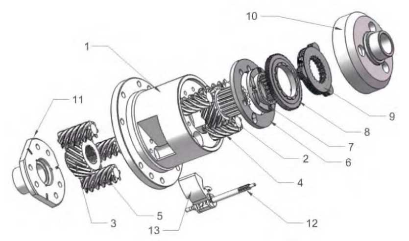
Assemble the parts in SolidWorks to form an assembly of helical gear limited-slip differential with locking function as shown in Figure 6, including differential housing 1, right half-shaft gear 2 and the right planetary gear set 4 engaged with it, left half-shaft gear 3 and the left planetary gear set 5 engaged with it, isolating ring 6, half-shaft cam 7, cam disc gear 8, friction plate set 9, upper end cover 10,Lower end cover 11, flywheel mechanism 12, release flip block 13.

Its specific functions are:
(1) Drive straight.The differential housing 1 rotates at a certain speed and the left and right half-shaft gears are stationary relative to the housing.
(2) Differential speed.When the vehicle is turning or the road conditions of the left and right wheels are different, take the left turn as an example, take the case 1 as the reference frame, the right half-shaft gear 2 turns forward at angular speed and the left half-shaft gear 3 turns backwards at the same angular speed to realize the differential function.
(3) Limit slip.In case of wheel slip, the half-shaft gears 2 and 3 rotate at a higher angular speed relative to the housing 1.Taking the wheel slip on the left side as an example, the gear meshing pair with large helical angle has a great internal friction force; the larger pressure angle of the gear also forces the planetary gear to press against the outer wall of the planetary gear bore during the meshing process; and the engagement of the helical gear will also have a great axial force. For each of the eight gears in the meshing system, there will be an end face pressing against the left end cover 11 and isolating ring 6. The resultant force of these forces,Limit the rotation of the entire planetary gear train, thereby limiting the speed of the left half-shaft gear 3 to significantly higher than that of the differential housing 1, and transfer the torque to the right half-shaft gear 2 to limit the left wheel slip and to transfer the torque to the right wheel.
(4) Automatic locking.When the wheels encounter limit conditions, one side of the wheel is completely suspended.Taking the idling of the left wheel as an example, with housing 1 as the reference frame, the left half-shaft gear 3 idles forward at a large angular speed, and the right half-shaft gear 2 engaged by the planetary gear pair rotates in the opposite direction at the same angular speed, driving the high-speed rotation of the half-shaft cam 7 splined with the cam disc gear 8 matched with the half-shaft cam 7 cam.As the flywheel shaft gear on the flywheel mechanism 12 engages with the cam disc gear 8, it will drive the flywheel mechanism 12 to rotate at a high speed, resulting in the flywheel opening outwards due to a large centrifugal force and clipping on the release throwing block 13.Releasing the flip block from the housing 1 will cause the flywheel mechanism 12 to brake and thus the cam disc gear 8 to brake.While the half-shaft cam 7 still rotates at a certain speed, causing the cam disc gear 8 to move upwards along the cam guides of both cams, pressing the friction plate set 9 and the upper end cover 10 of the housing, the reaction force of the housing makes the half-shaft cam 7 and the wheel 2 of the half-shaft splined with it decelerate to stop moving, thus the left and right half-shaft gears are stationary with respect to the housing 1, thus realizing the locking function and keeping the speed of the left and right wheels consistent.Get the vehicle out of trouble.
(5) Unlock automatically.When the speed of the differential is above a certain threshold value after locking, the contact flip block 13 overcomes the spring torsion and opens outwards under centrifugal force, so that the locking mechanism 12 is no longer attached to it, the flywheel shaft rotates freely, the cam disc gear 8 resets and the locking is released automatically.
