According to the structural design data, digital modeling is carried out in SolidWorks software.
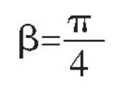
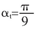
(1) Design of end profile.Setting helical angle of helical gear

, end pressure angle

, end modulus mt=3.75mm”Zt=6, the end indexing circle diameter d=22.5MM, Spiral Lead PZ=70.6858mm, end base circle diameter db=dcos alpha t=21.1431mmTherefore the radius of the base circle of the end face

And substitute it into equation (6) to get the involute equation of the designed tooth profile.In SolidWorks, equation-driven spline curve is used to plot the end profile of helical gear, and an involute curve is drawn in sketch. The involute curve is mirrored and a complete end profile is obtained according to the design parameters of crown circle, root circle, indexing circle and base circle.
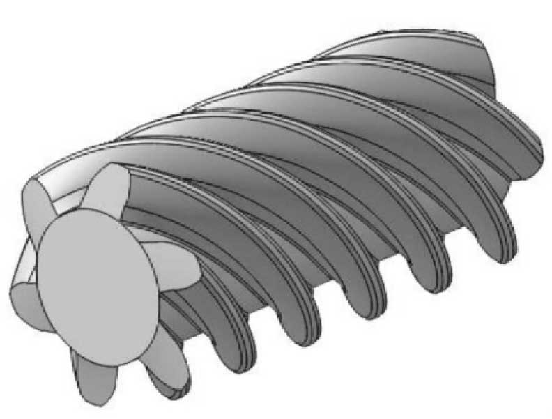
(2) Formation of helical teeth.Open the “Insert – Curve – Helix” option.The design parameters of helix in SolidWorks mainly include: pitch, number of turns, height, etc.By using the definition of pitch and number of turns, a single helical tooth is modeled, in which the pitch is the lead PZ in formula (8) and the cylindrical diameter of the helix is the D in formula (8); the end profile is scanned based on the helix to obtain a helical tooth.
(3) Formation of entity.A complete helical gear model with the corresponding number of teeth is obtained by using the circumferential array.The subsequent stretching can be performed to obtain the helical gear entity of the corresponding height.

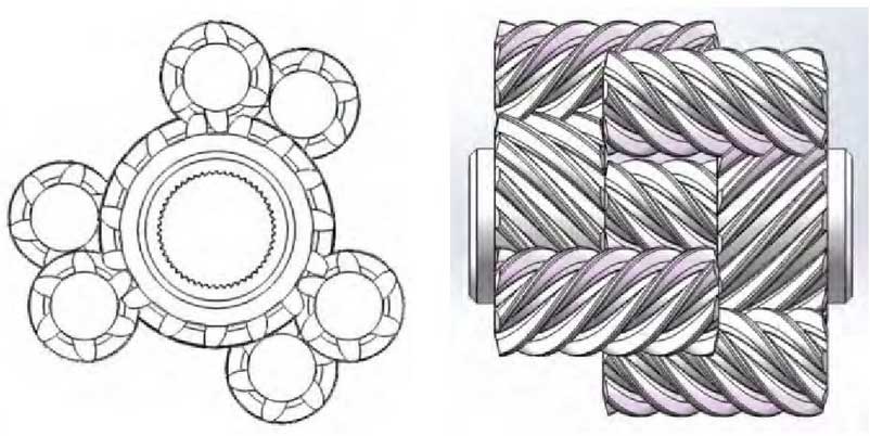
(4) Design of helical gear pair.In the same way, solid models of right and left half-shaft gears, three left-hand helical planetary gears and three right-hand helical planetary gears of limited-slip differential can be established [8].The engagement of the helical gears is shown in the figure.

