
Gear mechanisms are among the most critical and widely used forms of mechanical transmission. Their ability to maintain a constant transmission ratio, transmit large amounts of power, provide high kinematic accuracy and efficiency, operate reliably over long service lives, and offer compact designs makes them indispensable in modern machinery. Depending on the relative orientation of the shaft axes, gears can be classified into parallel-axis (cylindrical gears), intersecting-axis (bevel gears), and skew-axis (e.g., hypoid gears) types. Based on the tooth profile, common types include involute, cycloidal, circular-arc, and double-circular-arc cylindrical gears. Among these, the involute profile offers significant advantages over cycloidal or circular-arc profiles in terms of load capacity, manufacturability, and insensitivity to center-distance deviations. Consequently, involute cylindrical gears—including spur, helical, and herringbone gears—are predominant in engineering practice.
In this article, I present a comprehensive analysis of herringbone gears, covering their geometric formation, distinct advantages, design considerations, and various manufacturing methods. The discussion is supported by tables, formulas, and quantitative comparisons to provide a deep understanding of this advanced gear type.
Formation of Involute Tooth Surfaces
The formation of an involute curve can be described by taking a straight line that rolls without slipping on a circle (the base circle). Any point on the line traces an involute. Extending this principle to three dimensions: when a plane rolls without slipping on a cylinder (the base cylinder), any straight line on the plane generates an involute surface. If that line is parallel to the axis of the base cylinder, the resulting surface forms a spur gear tooth. If the line is inclined at an angle β (the helix angle) to the axis, the resulting surface is that of a helical gear tooth.
For a herringbone gear, the tooth is essentially a pair of helical gears with opposite helix angles machined on the same blank. The left-hand and right-hand sections share a common centerline, and the opposing axial thrusts cancel each other out.
Key parametric equations for an involute curve in the transverse plane are:
$$ \begin{aligned}
x(\theta) &= r_b (\cos\theta + \theta \sin\theta) \\
y(\theta) &= r_b (\sin\theta – \theta \cos\theta)
\end{aligned} $$
where \( r_b \) is the base circle radius and \( \theta \) is the roll angle. For a helical tooth surface, the helix angle imposes a rotation along the face width, described by:
$$ z = \frac{b}{2\pi} \cdot \psi $$
where \( \psi \) is the angular progression along the helix and \( b \) is the face width.
Advantages of Herringbone Gear Transmissions
One of the fundamental merits of cylindrical gears is smooth transmission, which requires a contact ratio greater than unity. In spur gears, the contact ratio is solely the transverse contact ratio \( \epsilon_\alpha \). Helical gears introduce an additional overlap ratio \( \epsilon_\beta \), leading to a total contact ratio:
$$ \epsilon_\gamma = \epsilon_\alpha + \epsilon_\beta $$
where
$$ \epsilon_\beta = \frac{b \sin\beta}{\pi m_n} $$
Here, \( b \) is the face width, \( \beta \) the helix angle, and \( m_n \) the normal module. For a given width and helix angle, \( \epsilon_\beta \) can be made arbitrarily large in theory, but practical constraints limit \( \beta \) to a range of about 8°–17° for helical gears due to axial forces.
Herringbone gears overcome this limitation by splitting the tooth into two mirrored helices. The axial forces generated by the left-hand and right-hand sections are equal in magnitude and opposite in direction, thus canceling within the gear itself. This allows the designer to use much larger helix angles—typically 25° to 40°—without imposing additional axial loads on bearings. The result is a significantly higher total contact ratio:
$$ \epsilon_\gamma = \epsilon_\alpha + \epsilon_{\beta,\text{total}} $$
where \( \epsilon_{\beta,\text{total}} = 2 \cdot \frac{(b/2) \sin\beta}{\pi m_n} = \frac{b \sin\beta}{\pi m_n} \) (the same expression but with the full width). In many practical designs, \( \epsilon_\gamma \) can exceed 4 or 5, leading to exceptionally smooth and quiet operation, higher load capacity, and reduced noise and vibration.
The following Table 1 provides a quantitative comparison of key characteristics among spur, helical, and herringbone gears.
| Parameter | Spur Gear | Helical Gear | Herringbone Gear |
|---|---|---|---|
| Typical helix angle β | 0° | 8°–17° | 25°–40° |
| Axial thrust | None | Significant (requires thrust bearings) | Self-canceling (no net axial load) |
| Total contact ratio εγ | εα (≈1.2–1.8) | εα+εβ (≈2–3) | εα+εβ (≈3–6) |
| Noise and vibration | Moderate | Low | Very low (smooth and quiet) |
| Load capacity (for same size) | Baseline | ~20–30% higher | ~40–60% higher |
| Manufacturing difficulty | Easy | Moderate | High (requires precise alignment) |
Design Parameters and Their Influence on Performance
The selection of module, helix angle, face width, and number of teeth for a herringbone gear must account for the balance between strength, wear resistance, and manufacturability. The following design formulas are commonly used:
Bending strength (ISO 6336 / AGMA):
$$ \sigma_F = \frac{F_t}{b m_n} Y_F Y_S Y_\epsilon Y_\beta $$
where \( F_t \) is the tangential force, \( Y_F \) the form factor, \( Y_S \) the stress correction factor, \( Y_\epsilon \) the contact ratio factor, and \( Y_\beta \) the helix angle factor.
Surface durability (Hertzian contact stress):
$$ \sigma_H = Z_H Z_E Z_\epsilon Z_\beta \sqrt{\frac{F_t}{b d_1} \frac{u+1}{u}} $$
with \( Z_H \) the zone factor, \( Z_E \) the elastic coefficient, \( Z_\epsilon \) the contact ratio factor, \( Z_\beta \) the helix angle factor, \( d_1 \) the pitch diameter of the pinion, and \( u \) the gear ratio.
Minimum face width for continuous overlap:
To ensure that at least one pair of teeth is always in mesh across the entire width of the herringbone gear, the face width must satisfy:
$$ b \ge \frac{\pi m_n}{\sin\beta} $$
This is a more restrictive condition than for helical gears due to the dual helix layout.
Table 2 summarizes typical design parameters for industrial herringbone gear sets.
| Parameter | Symbol | Typical Range / Value |
|---|---|---|
| Normal module | mn | 2 – 20 mm |
| Helix angle | β | 25° – 40° |
| Face width | b | 40 – 400 mm |
| Pressure angle | αn | 20° (standard) or 22.5° / 25° for high load |
| Addendum coefficient | ha* | 1.0 (standard profile) |
| Clearance coefficient | c* | 0.25 – 0.35 |
| Tooth number ratio | u | 1 – 10 |
| Surface hardness (carburized) | HRC | 58 – 62 |
Manufacturing Methods for Herringbone Gears
The fabrication of herringbone gears is considerably more complex than that of ordinary helical gears, primarily due to the need to precisely align the two helical halves along a common centerline (the “herringbone gear centerline”). This centerline must lie on the mid-plane of the gear blank, and the tolerances are typically within a few hundredths of a millimeter. Below I describe the most common manufacturing approaches classified by heat treatment state.
Soft Teeth (Surface Hardness < 350 HB)
1. Form milling with finger cutters on CNC machining centers.
In this method, a finger-shaped cutter travels along the tooth space profile. The gear accuracy is largely dependent on the cutter geometry. Typically, the achieved precision is around DIN 8 (AGMA 9-10). The centerline position can be controlled accurately because the tool path is programmed based on the blank reference. The main drawback is low productivity, as each tooth space must be cut individually. Table 3 lists representative parameters.
| Parameter | Value / Description |
|---|---|
| Machine tool | 5-axis CNC machining center |
| Cutter type | Finger cutter (single-lip or multi-lip) |
| Typical accuracy | DIN 8 (ISO 1328) |
| Centreline deviation | ±0.02 – 0.05 mm |
| Material removal rate | Low (10 – 30 mm³/min) |
| Setup time | Moderate (requires alignment of cutter axis with gear axis) |
2. Hobbing on CNC gear hobbing machines.
This is the most productive method for soft herringbone gears. Modern CNC hobbing machines often include a dedicated herringbone gear function that synchronizes the hob movement with the worktable feed to generate both left and right helices in a single clamping. The key is to input the exact mounting height of the gear blank to ensure the centerline falls precisely at the intersection of the two helical cuts. If the machine lacks this special function, the operator must manually mark the centerline on the blank and align the hob during the left and right cutting passes. The accuracy then depends on marking precision and operator skill. Typical hobbed herringbone gears achieve DIN 7 (AGMA 11-12).
| Parameter | Value / Description |
|---|---|
| Machine tool | CNC gear hobbing machine (with herringbone function) |
| Hob type | Single-start or multi-start, ground profile |
| Typical accuracy | DIN 7 (ISO 1328) |
| Centreline control | ±0.01 – 0.03 mm (with automatic function); ±0.05 – 0.10 mm (manual marking) |
| Productivity | High (2 – 5 minutes per tooth for medium-sized gears) |
Hard Teeth (Surface Hardness ≥ 58 HRC)
Hard herringbone gears are typically case-carburized and then ground to achieve high precision and surface integrity. Two typical heat treatment routes exist:
- Nitriding: Tooth profile is cut before nitriding; the soft machining methods above apply. Nitriding causes minimal distortion, so the final geometry is essentially the soft-machined shape.
- Carburizing + hardening: After carburizing and quenching, the gear must be finish-ground to remove distortion and achieve the specified accuracy. Grinding is the only practical method for finishing hard herringbone gears to high precision (DIN 5 or better).
Grinding of herringbone gears is performed on CNC gear grinding machines equipped with specialized software to handle the dual helix. The most common grinding process uses a threaded grinding wheel (continuous generating grinding) or a form wheel (profile grinding). The centerline can be adjusted during setup to compensate for distortion from heat treatment, but the adjustment range is limited by the grinding stock (typically 0.1 – 0.3 mm per flank). Therefore, the rough machining accuracy (hobbing) must be kept within tight tolerances. Table 5 compares the key aspects of grinding versus soft machining.
| Parameter | Soft Hobbing / Milling | Grinding (carburized) |
|---|---|---|
| Typical accuracy (DIN) | 7 – 8 | 5 – 4 |
| Surface roughness Ra | 1.6 – 3.2 μm | 0.4 – 0.8 μm |
| Heat treatment distortion | N/A (before HT) | Corrected by grinding |
| Centreline adjustment | No (fixed by setup) | Yes (limited range) |
| Equipment cost | Moderate | High (specialized gear grinding machine) |
| Cycle time (per tooth) | 2 – 10 min | 10 – 30 min |
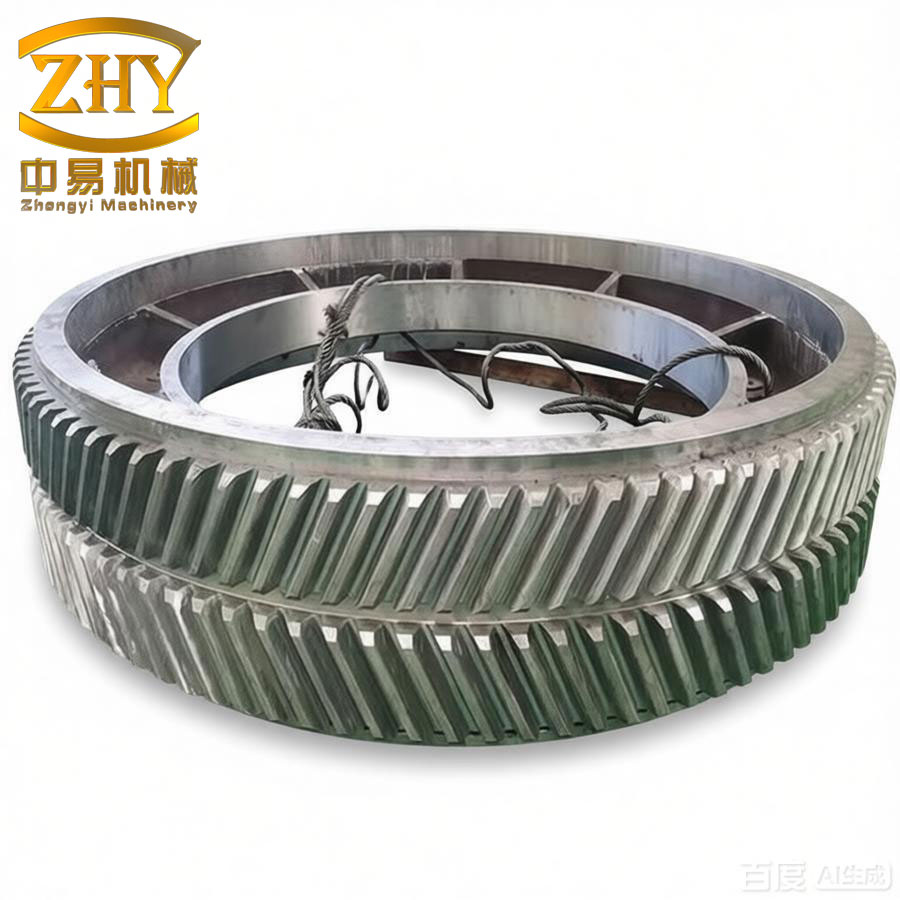
The following figure illustrates a typical herringbone gear set used in high-power industrial gearboxes.
Challenges in Centerline Control and Manufacturing Precision
The most difficult aspect of herringbone gear manufacturing is maintaining the correct location of the herringbone centerline (the axial plane where the left-hand and right-hand helices meet). This centerline must ideally lie at the mid-point of the gear’s face width. Deviations cause uneven load distribution, increased noise, and premature failure. The factors affecting centerline accuracy include:
- Blank alignment: The mounting height and parallelism of the gear blank relative to the machine axes must be set to within a few micrometers.
- Tool positioning: In hobbing, the hob must be positioned axially such that the cut tooth spaces on both sides meet exactly at the centerline. For machines without automatic functions, this requires careful marking and manual offset.
- Distortion from heat treatment: Carburizing and hardening can cause the centerline to shift. Grinding can compensate only if the shift is consistent and within the stock allowance.
- Machine rigidity and thermal stability: Large herringbone gears (e.g., 2 m diameter) require robust machines with temperature compensation to avoid positional drift during long cuts.
Table 6 lists typical tolerances for herringbone gear geometry according to ISO 1328 and DIN 3962 standards.
| Feature | Tolerance (μm) | Measurement Basis |
|---|---|---|
| Single pitch deviation (fpt) | ±5 – 12 | Per tooth, over 1 m diameter |
| Profile form deviation (ffα) | 6 – 15 | Involute check |
| Helix deviation (fHβ) | 4 – 10 | Over tooth width |
| Axial centerline position | ±10 – 30 | Relative to nominal mid-plane |
| Tooth thickness variation | 20 – 50 | Chordal measurement |
Future Trends in Herringbone Gear Manufacturing
With the increasing demand for compact, high-power-density gearboxes in wind turbines, marine propulsion, and industrial drives, herringbone gears are gaining wider adoption. Advances in multi-axis CNC gear hobbing and grinding machines, along with in-process measurement and compensation systems, are making it possible to produce large herringbone gears with DIN 3-4 precision routinely. The integration of digital twin technology allows offline simulation of the herringbone gear cutting process, ensuring the centerline is accurately predicted before the first chip is cut.
Additive manufacturing has also been explored for producing herringbone gear prototypes with complex internal geometries, although the surface integrity and fatigue performance of printed gears still lag behind conventionally machined ones. For high-volume production, the combination of precision hobbing (soft) followed by CBN grinding (hard) remains the state of the art.
Conclusion
Herringbone gears offer a unique combination of high load capacity, smooth and quiet operation, and self-canceling axial thrust, making them ideal for demanding power transmission applications. Their design requires careful selection of helix angle, face width, and module to maximize the contact ratio while controlling stresses. Manufacturing these gears presents significant challenges, especially in maintaining the precise centerline alignment of the two helical halves. Soft machining methods such as form milling and hobbing can achieve DIN 7-8 accuracy, while precision grinding of carburized gears can reach DIN 5 or better. The continued development of advanced CNC equipment and process control will further enhance the feasibility and cost-effectiveness of herringbone gear production, cementing their role as a key component in modern mechanical drive systems.
Through this article, I have provided a comprehensive overview of herringbone gear theory, design, and manufacturing. The formulas and tables presented can serve as a practical reference for engineers involved in gear transmission design and production.