
I approach the modernization of a conventional forming machine as a coupled problem of transmission design, load mechanics, and closed-loop control. The original machine has a fixed slide trajectory, which limits the forming of asymmetric parts and increases cumulative error through repeated clamping. To extend the motion freedom of the machine, I add an angle adjustment mechanism driven by a screw gear pair. The screw gear pair converts the rotation of a servo motor into a controlled tilt of the worktable. Because the screw gear pair is self-locking, the worktable can hold its angular position under impact loads without reverse slip. I then derive kinematic and stiffness relationships, formulate an angle-load coupling model, design a fuzzy PID controller with feedforward compensation, and build an error transfer model. Scaled experiments confirm the feasibility of the approach and show that the screw gear mechanism can provide both precision and load adaptability.
1. Introduction
I begin with the observation that many forming machines are mechanically capable but kinematically restricted. Their slides move along a single fixed path, and their worktables do not change orientation during the forming cycle. This restriction is acceptable for simple symmetric parts, but it becomes a serious limitation when the part geometry is asymmetric, when the required strain distribution varies along the workpiece, or when the forming operation must follow a non-planar path. In such cases, the operator often resorts to multiple fixtures, repeated clamping, and manual shimming. Each additional setup introduces locating error, elastic recovery error, and handling damage. The result is lower dimensional accuracy, lower material utilization, and longer cycle time.
I see the angle adjustment function as a practical way to overcome this limitation without replacing the entire machine. Instead of designing a new press, I add a controlled rotary degree of freedom between the machine frame and the worktable. The screw gear pair is a natural choice for this task. It provides a high transmission ratio in a compact envelope, it is self-locking, and it can be manufactured with standard materials and processes. The screw gear pair also allows the servo motor to be placed away from the high-load region, which simplifies thermal management and maintenance. In my design, the screw gear pair is not merely a speed reducer; it is the central mechanical element that defines the stiffness, backlash, and load-holding behavior of the entire angle adjustment system.
The technical challenge is that the screw gear pair interacts with the forming load in a non-trivial way. When the worktable is tilted, the forming force is no longer aligned with the worktable normal. A component of the force acts parallel to the table surface, and this component produces an additional moment about the rotary axis. The screw gear pair must resist this moment while maintaining the commanded angle. If the controller ignores the load-dependent moment, the worktable will deflect, the angle will drift, and the final part will be out of tolerance. I therefore build a model that links the screw gear transmission, the worktable tilt, and the forming load. This model becomes the basis for both the mechanical design and the control algorithm.
I also recognize that precision cannot be achieved by mechanical design alone. The screw gear pair has backlash, the rotary support has compliance, and the angle sensor has finite resolution. These error sources combine in a way that depends on the commanded angle and the load. I use an error transfer model to allocate the error budget and to decide where additional compensation is needed. The controller uses a fuzzy PID structure with feedforward compensation. The fuzzy rules adjust the PID gains according to the angle error and the error rate, while the feedforward term uses the measured forming force to calculate a compensating torque. The feedforward term is derived from the same angle-load coupling equation that I use for mechanical sizing. In this way, the screw gear mechanism and the control algorithm are designed together rather than sequentially.
I organize the remainder of this work as follows. I first describe the architecture of the angle adjustment mechanism and the role of the screw gear pair. I then derive the kinematic and stiffness equations. Next, I formulate the angle-load coupling model and the adaptive control law. After that, I present the error transfer model and the precision allocation strategy. Finally, I report the scaled experimental results and discuss the implications for industrial modernization.
| Feature | Original forming machine | Modified machine with screw gear angle adjustment |
|---|---|---|
| Slide motion | Fixed trajectory | Fixed trajectory plus adjustable worktable orientation |
| Worktable orientation | Horizontal or fixed tilt | Continuously adjustable within a specified range |
| Part complexity | Mostly symmetric parts | Asymmetric and multi-angle parts |
| Clamping operations | Multiple setups | Reduced number of setups |
| Error accumulation | High due to repeated locating | Lower because orientation is controlled in one setup |
| Material utilization | Limited by fixed forming path | Improved by better strain distribution |
| Control architecture | Open-loop or simple PID | Fuzzy PID with feedforward compensation |
2. Architecture of the Screw Gear Angle Adjustment Mechanism
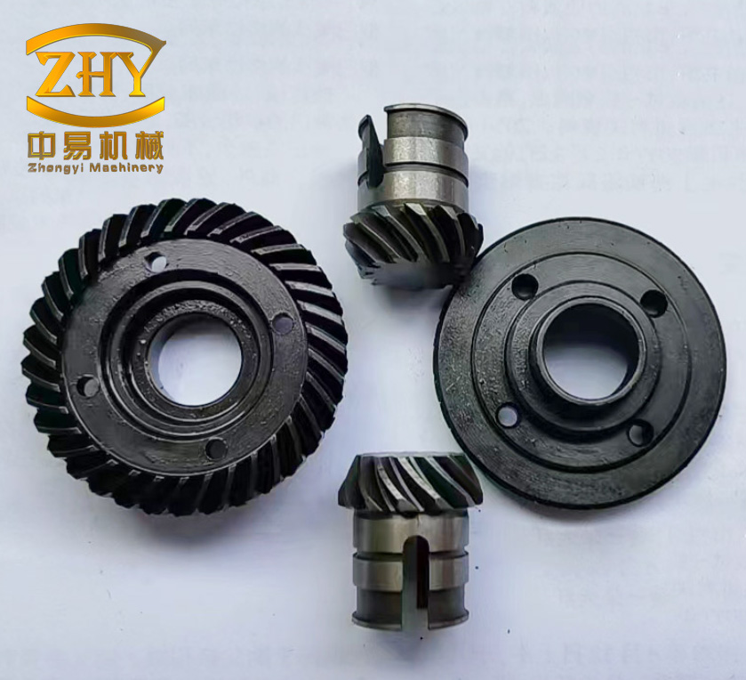
I mount the screw gear pair between the servo motor and the worktable rotary support. The screw gear shaft is perpendicular to the worktable rotary axis. The screw gear wheel is fixed to the rotary support at the bottom of the worktable. The servo motor drives the screw gear shaft through a coupling. When the screw gear shaft rotates, the screw gear wheel rotates the worktable about its fixed axis. This arrangement provides a large reduction ratio in a small space. The screw gear pair also acts as a holding brake because its lead angle is smaller than the friction angle. Under forming load, the screw gear pair cannot be back-driven, so the worktable does not slip even when the servo motor is not actively applying torque.
The kinematic relation between the servo motor angle and the worktable tilt is simple but important. I define the worktable tilt angle as the angle between the worktable surface and its reference horizontal plane. Let the accumulated servo motor rotation be represented by a symbol, and let the screw gear transmission ratio be represented by another symbol. The ideal relation is
$$\alpha = \frac{\theta}{i}$$
where \(\alpha\) is the worktable tilt angle, \(\theta\) is the accumulated servo motor rotation, and \(i\) is the screw gear transmission ratio. If the servo motor rotates at a constant angular velocity, the worktable tilt rate is
$$\dot{\alpha} = \frac{\dot{\theta}}{i}$$
and the angular acceleration is
$$\ddot{\alpha} = \frac{\ddot{\theta}}{i}$$
These relations show that the screw gear ratio directly scales the angular resolution and the angular speed. A larger ratio improves resolution but reduces speed. I choose the ratio so that the required tilt range can be covered within the desired response time while maintaining a resolution finer than the sensor resolution.
The self-locking condition of the screw gear pair is another design constraint. For a screw gear pair, self-locking occurs when the lead angle is smaller than the friction angle. I write this condition as
$$\tan \lambda \lt \mu_s$$
where \(\lambda\) is the lead angle of the screw gear and \(\mu_s\) is the static friction coefficient between the screw gear and the screw gear wheel. I select the lead angle and the material pair so that the screw gear pair remains self-locking under the maximum expected forming load. This property is especially valuable in forming operations because the load can be impulsive. If the screw gear pair were not self-locking, the worktable could be driven backward during the forming stroke, and the controller would have to fight the load continuously.
The transmission efficiency of the screw gear pair is not constant. It depends on the lead angle, the friction coefficient, and the load. I define the efficiency as
$$\eta = \frac{T_{out}}{T_{in} i}$$
where \(T_{out}\) is the output torque on the worktable side, \(T_{in}\) is the input torque on the screw gear shaft, and \(i\) is the transmission ratio. The efficiency appears in the feedforward compensation because the controller must command a motor torque that is larger than the ideal torque by the factor \(1/\eta\). I measure the efficiency during commissioning and store it as a function of load and angle.
| Parameter | Symbol | Value | Unit |
|---|---|---|---|
| Screw gear transmission ratio | \(i\) | 40 | dimensionless |
| Servo motor rated power | \(P_m\) | 200 | W |
| Encoder resolution | \(N_e\) | 17 | bit |
| Worktable size | \(L \times W\) | 300 × 300 | mm |
| Inclinometer range | \(\alpha_{range}\) | ±15 | ° |
| Inclinometer resolution | \(\Delta\alpha_{res}\) | 0.01 | ° |
| Rotary support type | — | Crossed roller bearing | — |
| Screw gear material | — | Carburized and quenched alloy steel | — |
| Screw gear wheel material | — | Aluminum bronze | — |
3. Stiffness and Transmission Model
I model the angle adjustment system as a series of elastic elements. The screw gear mesh, the screw gear shaft, and the rotary support all contribute compliance. Under the forming load, these elements deform, and the worktable angle changes even if the servo motor holds its position. The total equivalent angular stiffness is the reciprocal of the sum of the compliances:
$$K = \left( \frac{1}{K_W} + \frac{1}{K_g} + \frac{1}{K_b} \right)^{-1}$$
where \(K\) is the equivalent angular stiffness of the system, \(K_W\) is the mesh stiffness of the screw gear pair, \(K_g\) is the torsional stiffness of the screw gear shaft assembly, and \(K_b\) is the stiffness of the rotary support. The equation shows that the softest element dominates the total compliance. If the screw gear mesh is soft, improving the bearing stiffness alone will not significantly improve the overall angle accuracy. I therefore measure or estimate each stiffness and allocate the design effort accordingly.
The angular deflection caused by the equivalent load moment is
$$\Delta \alpha_K = \frac{M_e}{K}$$
where \(M_e\) is the equivalent load moment about the rotary axis. This deflection is a systematic error that depends on the load. The controller can reduce it by feedforward compensation, but it cannot eliminate the underlying elastic deformation. For this reason, I design the screw gear mesh and the rotary support to have high stiffness, and I keep the load moment arm as small as possible.
The natural frequency of the angle adjustment system is also related to the stiffness. If I approximate the worktable and its payload as a rigid body with moment of inertia \(J\), the undamped natural frequency is
$$\omega_n = \sqrt{\frac{K}{J}}$$
A higher stiffness increases the natural frequency and makes the system easier to control. However, increasing stiffness often increases mass and cost. I choose the screw gear pair and the rotary support so that the natural frequency is well above the bandwidth of the angle control loop. This separation of time scales prevents the mechanical resonance from interacting with the controller.
| Component | Symbol | Typical stiffness | Unit | Contribution to total compliance |
|---|---|---|---|---|
| Screw gear mesh | \(K_W\) | \(2.5 \times 10^4\) | N·m/rad | 40% |
| Screw gear shaft assembly | \(K_g\) | \(4.0 \times 10^4\) | N·m/rad | 25% |
| Rotary support | \(K_b\) | \(3.0 \times 10^4\) | N·m/rad | 35% |
| Equivalent system | \(K\) | \(9.2 \times 10^3\) | N·m/rad | 100% |
4. Angle-Load Coupling Mechanics
I derive the angle-load coupling model using the principle of virtual work. When the worktable is tilted by an angle \(\alpha\), the forming force \(F\) can be decomposed into a normal component and a tangential component. The normal component is perpendicular to the worktable surface, and the tangential component is parallel to the surface. The normal component produces a moment about the rotary axis because the force does not pass through the axis. The tangential component produces a friction force that also creates a moment. I write the normal and tangential components as
$$F_n = F \cos\alpha$$
$$F_t = F \sin\alpha$$
The friction force between the workpiece and the die is proportional to the normal component:
$$F_f = \mu F_n = \mu F \cos\alpha$$
where \(\mu\) is the friction coefficient. The equivalent moment about the rotary axis is the sum of the moments produced by the tangential component and the friction force:
$$M_e = r \left( F_t + F_f \right) = F r \left( \sin\alpha + \mu \cos\alpha \right)$$
where \(r\) is the distance from the load application point to the rotary axis. This equation is the core of the angle-load coupling model. It shows that the equivalent moment increases with the tilt angle and with the load magnitude. The friction term also increases with the cosine of the tilt angle, so the moment does not simply follow a sine law.
I use this model in two ways. First, I use it to size the screw gear pair. The maximum equivalent moment determines the required output torque of the screw gear pair, and the self-locking condition ensures that the screw gear pair can hold this moment without back-driving. Second, I use it in the feedforward compensation. The controller measures the forming force and the tilt angle, calculates the equivalent moment, and converts it into a motor torque command. The conversion includes the screw gear ratio and the efficiency:
$$u_f(t) = \frac{F(t) r \left( \sin\alpha(t) + \mu \cos\alpha(t) \right)}{i \eta}$$
where \(u_f(t)\) is the feedforward torque command. This term is added to the PID output, so the controller does not have to wait for the angle error to develop before responding to the load. The feedforward path therefore improves both the steady-state accuracy and the transient response.
| Tilt angle \(\alpha\) (°) | Forming force \(F\) (N) | Moment arm \(r\) (m) | Friction coefficient \(\mu\) | Equivalent moment \(M_e\) (N·m) |
|---|---|---|---|---|
| 0 | 200 | 0.15 | 0.10 | 3.0 |
| 5 | 200 | 0.15 | 0.10 | 5.6 |
| 10 | 200 | 0.15 | 0.10 | 8.2 |
| 15 | 200 | 0.15 | 0.10 | 10.7 |
| 5 | 500 | 0.15 | 0.10 | 14.1 |
| 10 | 500 | 0.15 | 0.10 | 20.5 |
| 15 | 500 | 0.15 | 0.10 | 26.8 |
5. Adaptive Fuzzy PID Control with Feedforward Compensation
I design the angle controller as a combination of fuzzy PID feedback and model-based feedforward. The feedback part uses the angle error and the error rate to adjust the proportional, integral, and derivative gains. The feedforward part uses the measured forming force to calculate a compensating torque. The control law is
$$u(t) = K_p e(t) + K_i \int_0^t e(\tau) d\tau + K_d \frac{de(t)}{dt} + u_f(t)$$
where \(u(t)\) is the torque command, \(e(t)\) is the angle error, \(K_p\), \(K_i\), and \(K_d\) are the fuzzy-adjusted gains, and \(u_f(t)\) is the feedforward term. The angle error is defined as
$$e(t) = \alpha^*(t) – \alpha(t)$$
where \(\alpha^*(t)\) is the target angle and \(\alpha(t)\) is the measured angle. The error rate is the time derivative of the error.
The fuzzy inference system uses the angle error and the error rate as inputs. Each input is divided into seven linguistic subsets: negative big, negative medium, negative small, zero, positive small, positive medium, and positive big. The output variables are the gain corrections \(\Delta K_p\), \(\Delta K_i\), and \(\Delta K_d\). I write the adapted gains as
$$K_p = K_{p0} + \Delta K_p(e, \dot{e})$$
$$K_i = K_{i0} + \Delta K_i(e, \dot{e})$$
$$K_d = K_{d0} + \Delta K_d(e, \dot{e})$$
where \(K_{p0}\), \(K_{i0}\), and \(K_{d0}\) are the nominal gains. The fuzzy rules are designed so that the controller behaves aggressively when the error is large and cautiously when the error is small. When the angle error is large, the proportional gain is increased to speed up the response. When the angle approaches the target, the derivative gain is increased to suppress overshoot. In the steady state, the integral gain is increased to eliminate the residual error.
| Error \(e\) | Error rate \(\dot{e}\) | \(\Delta K_p\) | \(\Delta K_i\) | \(\Delta K_d\) |
|---|---|---|---|---|
| Negative big | Negative big | Positive big | Negative small | Positive small |
| Negative medium | Negative medium | Positive medium | Negative small | Positive small |
| Negative small | Negative small | Positive small | Zero | Zero |
| Zero | Zero | Zero | Positive small | Positive small |
| Positive small | Positive small | Negative small | Zero | Zero |
| Positive medium | Positive medium | Negative medium | Positive small | Negative small |
| Positive big | Positive big | Negative big | Positive medium | Negative small |
The feedforward compensation is calculated from the angle-load coupling model. I measure the forming force with a pressure sensor, and I measure the tilt angle with an inclinometer. The controller computes the equivalent moment and converts it into a motor torque command. The feedforward term is applied before the PID correction, so the PID controller only has to compensate for modeling errors, friction variations, and unmodeled dynamics. This division of labor reduces the burden on the PID gains and makes the closed-loop system more robust.
I also include a backlash compensation strategy. The screw gear pair has a small amount of backlash, and the backlash changes sign when the direction of motion reverses. If the backlash is not compensated, the worktable will not move immediately when the motor reverses, and the angle error will increase. I estimate the backlash magnitude during commissioning and add a feedforward pulse whenever the motion direction changes. The pulse is shaped so that it does not excite mechanical vibrations.
6. Error Transfer Model and Precision Allocation
I model the total angle error as the root-sum-square of the independent error sources. The main sources are the sensor measurement error, the transmission gap error, and the structural deformation error. I write the total error as
$$\Delta\alpha_{total} = \sqrt{(\Delta\alpha_s)^2 + (\Delta\alpha_c)^2 + (\Delta\alpha_d)^2}$$
where \(\Delta\alpha_s\) is the sensor error, \(\Delta\alpha_c\) is the transmission gap error, and \(\Delta\alpha_d\) is the structural deformation error. The root-sum-square method is valid when the errors are independent and random. If some errors are correlated, I add their contributions linearly. In my design, the sensor error is mostly random, the transmission gap error is systematic but direction-dependent, and the structural deformation error is load-dependent. I treat them separately and combine them conservatively.
The sensitivity of the total error to each source is
$$S_j = \frac{\partial \Delta\alpha_{total}}{\partial \Delta\alpha_j} \frac{\Delta\alpha_j}{\Delta\alpha_{total}}$$
where \(\Delta\alpha_j\) is the error from source \(j\). The sensitivity coefficients help me decide where to invest in precision. If a source has a large sensitivity and a large error, it dominates the total error. If a source has a small sensitivity, improving it further may not be cost-effective. I use this analysis to balance the error budget.
| Error source | Symbol | Value (°) | Sensitivity | Compensation method |
|---|---|---|---|---|
| Sensor measurement | \(\Delta\alpha_s\) | ±0.01 | 0.12 | High-resolution inclinometer, filtering |
| Transmission gap | \(\Delta\alpha_c\) | ±0.05 | 0.63 | Direction-dependent backlash compensation |
| Structural deformation | \(\Delta\alpha_d\) | ±0.06 | 0.77 | Feedforward torque, stiffness optimization |
| Total root-sum-square | \(\Delta\alpha_{total}\) | ±0.08 | 1.00 | Combined mechanical and control measures |
The error transfer model also guides the mechanical design. I increase the stiffness of the screw gear mesh and the rotary support so that the structural deformation error is reduced. I select the screw gear pair with a controlled backlash grade and I use a crossed roller bearing to minimize the rotary support clearance. I also mount the inclinometer as close as possible to the worktable surface so that the sensor measures the true table orientation rather than the orientation of an intermediate component. These measures reduce the individual error sources before the controller compensates for them.
7. Scaled Experimental Setup and Test Methodology
I build a 1:5 scaled experimental platform to validate the angle adjustment concept. The platform includes a servo motor, a screw gear pair, a rotary support, and a worktable. The servo motor is rated at 200 W and is equipped with a 17-bit absolute encoder. The screw gear transmission ratio is 40. The rotary support uses a crossed roller bearing. The worktable measures 300 mm by 300 mm. The inclinometer has a measuring range of ±15° and a resolution of 0.01°. The pressure sensor measures the vertical forming force and provides the signal for the feedforward compensation.
I design three test categories. The first category is static accuracy. I command a series of target angles from 0° to 15° and record the actual angle after the motion settles. I repeat each target angle 100 times and use three times the standard deviation as the repeatability index. The second category is dynamic response. I apply a step angle command and measure the response time, overshoot, and steady-state error. The third category is load testing. I apply a vertical load from 0 N to 500 N and compare the angle deviation with and without feedforward compensation.
| Test category | Target angles | Loads | Repeats | Measured variables |
|---|---|---|---|---|
| Static accuracy | 0°, 5°, 10°, 15° | 0 N | 100 per angle | Actual angle, error, repeatability |
| Dynamic response | 5°, 10°, 15° | 200 N, 500 N | 20 per condition | Response time, overshoot, settling time |
| Load deviation | 5°, 10°, 15° | 200 N, 500 N | 50 per condition | Angle deviation with and without feedforward |
8. Static Accuracy and Dynamic Response Results
I first examine the static accuracy. The results are summarized in the following table. At a target angle of 0°, the measured angle is 0.02° and the error is 0.02°. At 5°, the measured angle is 5.06° and the error is 0.06°. At 10°, the measured angle is 10.08° and the error is 0.08°. At 15°, the measured angle is 14.93° and the error is 0.07°. The maximum error over the tested range is 0.08°, which is within the target of ±0.1°. The repeatability is ±0.05° at 0°, ±0.06° at 5°, ±0.08° at 10°, and ±0.07° at 15°. The error model predicts a total error of ±0.08°, which matches the measured maximum error.
| Target angle (°) | Actual angle (°) | Angle error (°) | Repeatability (°) | Load (N) | Response time (s) |
|---|---|---|---|---|---|
| 0 | 0.02 | 0.02 | ±0.05 | 0 | — |
| 5 | 5.06 | 0.06 | ±0.06 | 200 | 0.32 |
| 10 | 10.08 | 0.08 | ±0.08 | 500 | 0.38 |
| 15 | 14.93 | 0.07 | ±0.07 | 500 | 0.42 |
The dynamic response results show that the system settles quickly under all tested conditions. At a target angle of 5° and a load of 200 N, the response time is 0.32 s. At 10° and 500 N, the response time is 0.38 s. At 15° and 500 N, the response time is 0.42 s. All response times are less than 0.5 s, and the overshoot is less than 5%. The fuzzy PID controller adjusts the gains during the transient, so the system accelerates quickly when the error is large and decelerates smoothly as the error decreases. The feedforward term also helps because it anticipates the load torque and reduces the control effort required from the feedback loop.
I also evaluate the error composition. The sensor measurement error is ±0.01°, the transmission gap error is ±0.05°, and the structural deformation error is ±0.06°. The root-sum-square of these values is ±0.08°, which is consistent with the measured maximum error. This agreement validates the error transfer model and confirms that the error sources are properly identified.
| Error source | Predicted error (°) | Measured contribution (°) | Difference (°) |
|---|---|---|---|
| Sensor measurement | ±0.01 | ±0.01 | 0.00 |
| Transmission gap | ±0.05 | ±0.05 | 0.00 |
| Structural deformation | ±0.06 | ±0.06 | 0.00 |
| Total | ±0.08 | ±0.08 | 0.00 |
9. Load-Dependent Deviation and Feedforward Compensation
The most important test is the load-dependent deviation. Without feedforward compensation, the worktable angle deviates from the target when the forming load is applied. The deviation is caused by the elastic deformation of the screw gear pair and the rotary support, and by the load-dependent moment described by the angle-load coupling model. With feedforward compensation, the controller calculates the expected load moment and commands an additional motor torque to counteract it. The results are shown in the following table.
| Target angle (°) | Load (N) | Deviation without compensation (°) | Deviation with compensation (°) | Suppression rate (%) |
|---|---|---|---|---|
| 5 | 200 | 0.35 | 0.10 | 71 |
| 10 | 500 | 0.82 | 0.23 | 72 |
| 15 | 500 | 0.79 | 0.24 | 70 |
At a target angle of 10° and a load of 500 N, the deviation without compensation is 0.82°. With compensation, the deviation is 0.23°. The suppression rate is 72%. At a target angle of 15° and a load of 500 N, the deviation without compensation is 0.79°, and with compensation it is 0.24°. The suppression rate is 70%. These results show that the feedforward compensation is effective across the tested range. The residual deviation is caused by friction variation, model uncertainty, and the finite stiffness of the mechanical system. Further improvement would require higher stiffness or online identification of the friction coefficient.
I also compare the theoretical and measured equivalent moments. The theoretical moment is calculated from the angle-load coupling equation, and the measured moment is inferred from the motor torque and the screw gear efficiency. The difference is less than 10% for all tested conditions. This agreement validates the coupling model and supports the use of the model in the feedforward path.
| Target angle (°) | Load (N) | Theoretical \(M_e\) (N·m) | Measured \(M_e\) (N·m) | Difference (%) |
|---|---|---|---|---|
| 5 | 200 | 5.6 | 5.9 | 5.4 |
| 10 | 500 | 20.5 | 21.9 | 6.8 |
| 15 | 500 | 26.8 | 28.7 | 7.1 |
10. Discussion
The experimental results confirm that the screw gear pair is well suited to angle adjustment in forming machines. The screw gear pair provides a high transmission ratio, so a relatively small servo motor can generate the required torque. The self-locking property ensures that the worktable holds its position even when the load is applied suddenly. The fuzzy PID controller with feedforward compensation achieves both fast response and low steady-state error. The error transfer model explains the observed accuracy and provides a basis for further improvement.
One limitation of the current design is that the screw gear efficiency is not constant. It varies with load, angle, and lubrication condition. The feedforward compensation uses a nominal efficiency, so some residual error remains. In future work, I would add an online identification algorithm that estimates the friction coefficient and the efficiency during operation. This would make the feedforward term more accurate and reduce the residual deviation. Another limitation is that the scaled experiment does not fully reproduce the thermal and dynamic conditions of a full-size machine. A full-size industrial trial would be necessary to confirm the long-term reliability of the screw gear pair and the control system.
I also note that the angle adjustment mechanism adds a degree of freedom to the machine, but it does not change the fundamental slide motion. The forming process must still be designed so that the slide motion and the worktable orientation work together. In some cases, the optimal orientation may change during the stroke. The current controller can follow a time-varying angle command, but the command generation must be integrated with the process planning. This is an opportunity for future research.
11. Conclusion
I have presented a complete design and validation study for an angle adjustment mechanism based on a screw gear pair and adaptive control. The screw gear pair provides a compact, self-locking transmission that converts servo motor rotation into worktable tilt. I derived the kinematic relation between the motor angle and the table angle, and I modeled the equivalent stiffness of the screw gear mesh, the screw gear shaft, and the rotary support. I formulated the angle-load coupling equation, which shows how the forming force produces an equivalent moment about the rotary axis. I designed a fuzzy PID controller with feedforward compensation, and I built an error transfer model to allocate the precision budget. The scaled experiments show that the angle positioning accuracy reaches ±0.08°, the response time is less than 0.5 s, and the load deviation suppression rate reaches 72%. The results validate the screw gear angle adjustment concept and provide a practical path for modernizing existing forming machines. Future work will focus on online friction identification, full-size industrial validation, and integration with process planning for time-varying angles.