
I have focused my recent research on the meshing performance of face gears because these components offer high contact ratio, strong load-carrying capacity, and significant weight reduction potential in aerospace and automotive transmissions. In practical applications, however, face gears are highly sensitive to installation misalignment, axial displacement, and support deformation. Such errors can shift the contact pattern toward the tooth edges, causing edge contact, scoring, and premature failure. Because the pressure angle of face gears varies along the tooth width, their contact behavior differs fundamentally from that of conventional cylindrical gears. Therefore, I propose a high-order segmented topology modification method that is based on a predefined contact path. This method aims to reduce sensitivity to installation errors, optimize load distribution, and improve the overall meshing performance of face gear pairs.
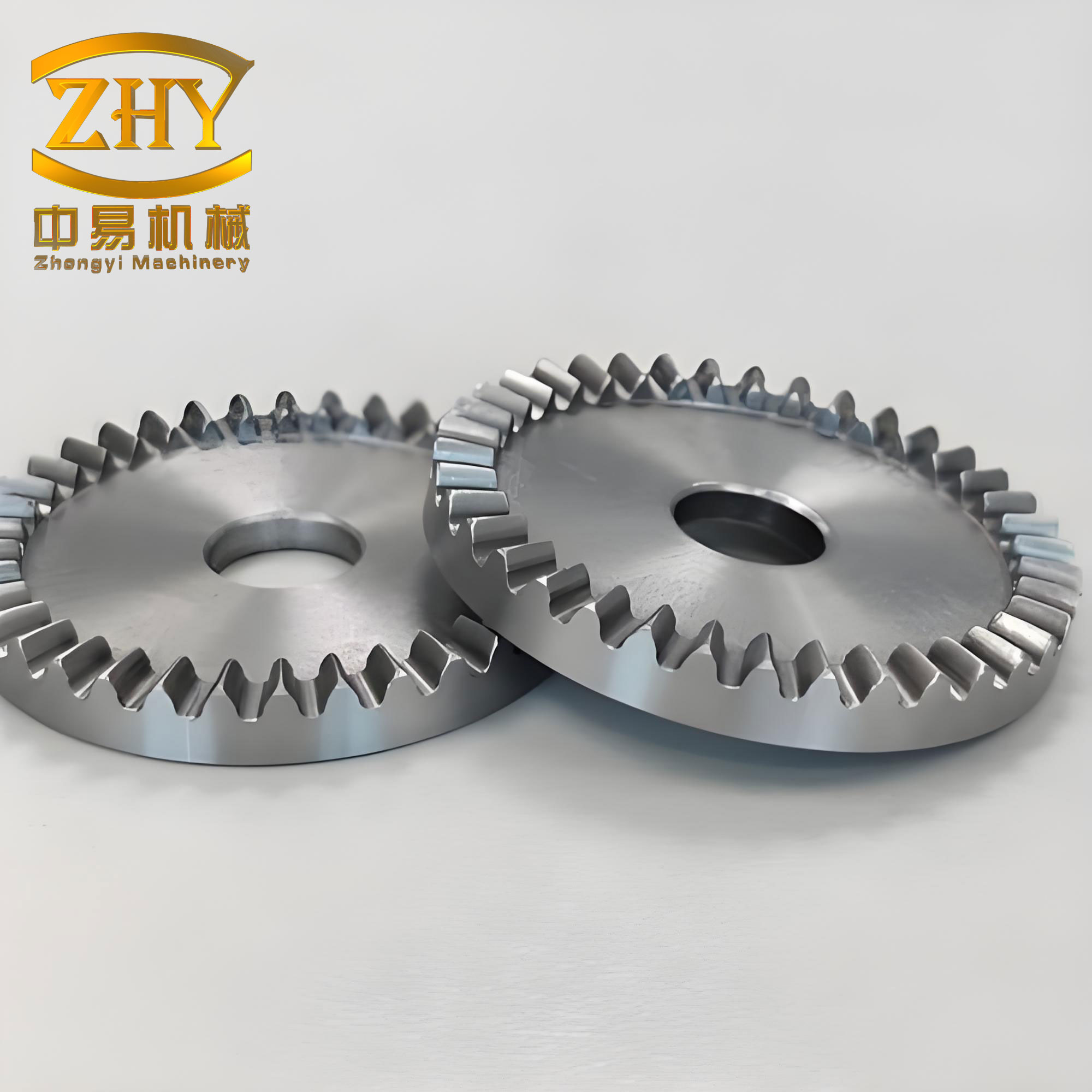
My approach combines tooth contact analysis (TCA) and finite element analysis (FEA) to evaluate the modified tooth surfaces under both unloaded and loaded conditions. I design second-order and fourth-order segmented modification functions along the predefined contact path and the instantaneous contact line. By superimposing these modification functions onto the theoretical pinion tooth surface, I obtain a controlled ease-off topology that produces a desired contact trace and a high-order transmission error curve. I then compare second-order, fourth-order, and fourth-order segmented modifications under different installation error conditions. The results show that the fourth-order segmented modification effectively reduces contact stress, bending stress, and loaded transmission error while extending the contact pattern from the inner root to the outer tip of the face gear tooth.
The remainder of this article is organized as follows. I first derive the theoretical tooth surface equations for face gears generated by a shaping cutter. Next, I present the rotational projection method, the predefined contact path, and the high-order segmented modification functions. I then establish the TCA model with installation errors and investigate the influence of path angle, modification length, modification order, and maximum modification amount. Finally, I build a five-tooth finite element model to analyze the loaded contact characteristics of face gear pairs under different modification strategies.
1. Theoretical Tooth Surface Equations for Face Gears
I begin with the generation principle of face gears. A face gear is typically cut by a shaping cutter that is a cylindrical gear. The cutter and the face gear rotate in a fixed ratio during the shaping process. I define the coordinate system \(S_S\) attached to the cutter and the coordinate system \(S_2\) attached to the face gear. The angle between the cutter axis and the face gear axis is denoted by \(\gamma_m\), and the pitch radius of the cutter is \(r_{pS}\). The instantaneous generating surface of the cutter is a cylindrical gear tooth surface. Its position vector and normal vector in \(S_S\) are expressed as functions of the surface parameters \(u_S\) and \(l_S\):
$$ \mathbf{r}_S = \mathbf{r}_S(u_S, l_S), \quad \mathbf{n}_S = \mathbf{n}_S(u_S, l_S). $$
When the subscript \(S\) is replaced by \(1\), the same expressions represent the pinion tooth surface. According to the theory of spatial meshing, the meshing point between the cutter and the face gear must satisfy the equation of meshing:
$$ f(u_S, l_S, \phi_S) = 0, $$
where \(\phi_S\) is the rotation angle of the cutter. The family of cutter surfaces and their normal vectors in the face gear coordinate system are obtained by coordinate transformation:
$$ \mathbf{r}_2(u_S, l_S, \phi_S) = \mathbf{M}_{2S} \mathbf{r}_S(u_S, l_S), $$
$$ \mathbf{n}_2(u_S, l_S, \phi_S) = \mathbf{L}_{2S} \mathbf{n}_S(u_S, l_S), $$
where \(\mathbf{M}_{2S}\) is the coordinate transformation matrix from \(S_S\) to \(S_2\), and \(\mathbf{L}_{2S}\) is the corresponding vector transformation matrix. By combining the equation of meshing with the above transformations, I obtain the theoretical position vector and normal vector of the face gear tooth surface:
$$ \mathbf{r}_2 = \mathbf{r}_2(u_2, l_2), \quad \mathbf{n}_2 = \mathbf{n}_2(u_2, l_2). $$
The basic parameters of the face gear pair used in my study are listed in Table 1. These parameters are representative of a medium-sized aerospace transmission. The face gear has 142 teeth, and the pinion has 21 teeth. The module is 3.9 mm, the pressure angle is 25°, and the shaft angle is 90°. The pinion face width is 55 mm, while the face gear extends from an inner diameter of 507 mm to an outer diameter of 610 mm.
| Parameter | Value | Parameter | Value |
|---|---|---|---|
| Module \(m_n\) | 3.9 mm | Pinion face width \(b_1\) | 55 mm |
| Pressure angle \(\alpha_n\) | 25° | Face gear inner diameter \(D_1\) | 507 mm |
| Shaft angle \(\gamma_m\) | 90° | Face gear outer diameter \(D_2\) | 610 mm |
| Pinion teeth \(z_1\) | 21 | Face gear teeth \(z_2\) | 142 |
These parameters define the geometric basis for the contact path design and the modification functions that I develop in the next section. I note that the face gear tooth surface is not a simple developable surface; its curvature and pressure angle change continuously along the tooth width. Therefore, any modification strategy must account for the local geometry to avoid unexpected edge contact.
2. High-Order Segmented Topology Modification
My modification strategy starts from an analysis of the basic contact trace of the face gear pair. Under ideal conditions without modification and without installation error, the contact path and the instantaneous contact line have specific orientations. When the pinion is the driving member, the instantaneous contact line forms an angle with the tooth tip, and this angle varies as the contact moves from the outer diameter to the inner diameter of the face gear. To reduce meshing impact at the beginning and end of contact and to avoid edge contact caused by installation errors, I propose a topology modification that is applied along both the contact trace and the instantaneous contact line.
2.1 Rotational projection and predefined contact path
I use a rotational projection method to map the pinion tooth surface onto a plane. The coordinate system \(S_1\) is fixed to the pinion, and its \(z_1\) axis coincides with the pinion axis. An auxiliary coordinate system \(S_0\) is introduced. The origin of the projection coordinate system \(S_p\) is the center point \(O_p\) of the pinion tooth surface. The \(x_p\) axis corresponds to the tooth width direction, and the \(y_p\) axis corresponds to the tooth height direction. The pinion face width is \(b_1\), and the pinion pitch radius is \(r_{p1}\). For any point on the pinion tooth surface, its projection coordinates in \(S_0\) are given by
$$ x_0(u_1, l_1) = z_1(u_1, l_1), $$
$$ y_0(u_1, l_1) = \sqrt{x_1^2(u_1, l_1) + y_1^2(u_1, l_1)}, $$
$$ z_0(u_1, l_1) = 0, $$
where \(x_1\), \(y_1\), and \(z_1\) are the coordinate components of the theoretical pinion position vector \(\mathbf{r}_1(u_1, l_1)\). The transformation to the projection coordinate system \(S_p\) is written as
$$ [x_p, y_p, z_p, 1]^T = \mathbf{M}_{p0} [x_0, y_0, z_0, 1]^T, $$
with the transformation matrix
$$ \mathbf{M}_{p0} = \begin{bmatrix}
1 & 0 & 0 & \frac{b_1}{2} \\
0 & 1 & 0 & -r_{p1} \\
0 & 0 & 1 & 0 \\
0 & 0 & 0 & 1
\end{bmatrix}. $$
On the projected tooth surface, I define a predefined contact path \(X_1\) and an instantaneous contact line \(X_2\). The angle of the contact path relative to the axis \(X_p\) is \(\xi\), and the angle of the instantaneous contact line relative to \(X_p\) is \(\eta\). For any point \(Q\) on the projected tooth surface, its projection coordinates along the contact path and the instantaneous contact line are
$$ x_1 = x_p \cos \xi – y_p \sin \xi, $$
$$ x_2 = \frac{x_p \sin \xi + y_p \cos \xi}{\sin(\xi + \eta)}. $$
These coordinates serve as the independent variables for the modification functions. By choosing \(\xi\) and \(\eta\), I can control the orientation of the contact pattern and the direction of the instantaneous contact line. This is particularly important for face gears because the contact path must be aligned with the local tooth geometry to avoid stress concentration.
2.2 Design of the modification functions
To achieve a smooth load transition at the beginning and end of meshing, I design separate modification functions along the contact path and the instantaneous contact line. The modification amount in the normal direction of the pinion tooth surface is denoted by \(Z_1\) for the contact path and \(Z_2\) for the instantaneous contact line. Along the contact path, I use a high-order segmented function. Let \(B_1\) and \(C_1\) be the projections of the tooth surface corner points \(B\) and \(C\) onto the contact path. Let \(B_0\) and \(C_0\) be the modification start points at the two ends of the contact path. The modification amounts at \(B_1\) and \(C_1\) are \(\Delta_B\) and \(\Delta_C\), respectively. The polynomial coefficients are \(a_{Bi}\) and \(a_{Ci}\), where \(i\) is the order of the modification function and \(i \ge 2\). The high-order segmented modification function along the contact path is
$$ z_1(x_1) = \begin{cases}
a_{Bi} (x_1 – x_{B0})^i, & x_{B1} \le x_1 < x_{B0}, \\
0, & x_{B0} \le x_1 < x_{C0}, \\
a_{Ci} (x_1 – x_{C0})^i, & x_{C0} \le x_1 \le x_{C1}.
\end{cases} $$
Along the instantaneous contact line, I use a second-order function. Let \(A_2\) and \(D_2\) be the projections of the tooth surface corner points \(A\) and \(D\) onto the instantaneous contact line. The modification amounts at these points are \(\Delta_A\) and \(\Delta_D\). The second-order modification function along the instantaneous contact line is
$$ z_2(x_2) = \begin{cases}
a_A x_2^2, & 0 \le x_2 \le x_{A2}, \\
a_D x_2^2, & x_{D2} \le x_2 < 0.
\end{cases} $$
The coefficients are determined by the maximum modification amounts and the modification lengths:
$$ a_{Bi} = \frac{\Delta_B}{(k_{Bi} \cdot \overline{B_1 O_1})^i}, \quad a_{Ci} = \frac{\Delta_C}{(k_{Ci} \cdot \overline{C_1 O_1})^i}, $$
$$ a_A = \frac{\Delta_A}{(\overline{A_2 O_2})^2}, \quad a_D = \frac{\Delta_D}{(\overline{D_2 O_2})^2}. $$
Here, \(k_{Bi}\) and \(k_{Ci}\) are the modification length coefficients along the contact path. They satisfy \(k_{Bi} = \overline{B_0 O_1} / \overline{B_1 O_1}\) and \(k_{Ci} = \overline{C_0 O_1} / \overline{C_1 O_1}\). When \(k_{Bi} < 1\) or \(k_{Ci} < 1\), the modification is segmented, meaning that the central region of the tooth surface remains unmodified or only lightly modified. This segmentation is a key feature of my method because it preserves a large contact area in the middle of the tooth while providing sufficient relief at the ends.
2.3 Modified tooth surface equation
I construct the modified tooth surface by superimposing the modification amounts from both directions onto the theoretical pinion tooth surface. The total modification amount at any point is
$$ \delta(u_1, l_1) = z_1(u_1, l_1) + z_2(u_1, l_1). $$
I then shift each point of the theoretical tooth surface along its original normal direction by the modification amount. The position vector of the modified pinion tooth surface is
$$ \mathbf{r}_m = \mathbf{r}_1 + \delta \cdot \mathbf{n}_1. $$
The corresponding normal vector is obtained from the partial derivatives:
$$ \mathbf{n}_m(u_1, l_1) = \frac{\partial \mathbf{r}_m}{\partial u_1} \times \frac{\partial \mathbf{r}_m}{\partial l_1}. $$
In these equations, \(\mathbf{r}_1\) and \(\mathbf{n}_1\) are the position vector and unit normal vector of the theoretical tooth surface. \(\mathbf{r}_m\) and \(\mathbf{n}_m\) are the position vector and unit normal vector of the modified tooth surface. The resulting modified surface is a true topological surface: every cross-section along the tooth width has a different profile modification. This is fundamentally different from conventional profile modification or lead modification, which are usually applied uniformly along one direction.
I have designed six modification cases to study the influence of different parameters. These cases are listed in Table 2. The contact path angle \(\xi\) ranges from 6.425° to 40°. The maximum modification amounts \(\Delta_{Bi}\) and \(\Delta_{Ci}\) range from 10 μm to 30 μm. The modification length coefficients \(k_{Bi}\) and \(k_{Ci}\) are either 1 (full modification) or 0.6 (segmented modification). In all cases, I use a fourth-order polynomial for the contact path modification.
| Case | \(\xi\) (°) | \(\Delta_{Bi}\) (μm) | \(\Delta_{Ci}\) (μm) | \(k_{Bi}\) | \(k_{Ci}\) |
|---|---|---|---|---|---|
| 1 | 6.425 | 10 | 10 | 1 | 1 |
| 2 | 20 | 10 | 10 | 1 | 1 |
| 3 | 40 | 10 | 10 | 1 | 1 |
| 4 | 6.425 | 20 | 20 | 1 | 1 |
| 5 | 6.425 | 30 | 30 | 1 | 1 |
| 6 | 6.425 | 10 | 10 | 0.6 | 0.6 |
These cases allow me to isolate the effects of contact path angle, modification amount, and segmentation. I now proceed to the tooth contact analysis to quantify how these parameters affect the contact trace, transmission error, and contact ratio.
3. Tooth Contact Analysis with Installation Errors
I establish a tooth contact analysis model that includes installation errors. The coordinate systems are defined as follows. \(S_1\) and \(S_2\) are rigidly connected to the pinion and the face gear, respectively. \(S_f\) is a fixed reference frame. The rotation angles of the pinion and the face gear are \(\phi_1\) and \(\phi_2\). I introduce auxiliary coordinate systems \(S_{10}\) and \(S_{20}\) to incorporate installation errors. The face gear axial offset is \(\Delta q\), the pinion axial offset is \(\Delta p\), the shaft angle error is \(\Delta \gamma\), and the center distance error is \(\Delta E\).
The position vectors and normal vectors of the modified pinion tooth surface and the face gear tooth surface are transformed into the fixed frame \(S_f\). They are denoted by \(\mathbf{r}_{f1}\), \(\mathbf{n}_{f1}\), \(\mathbf{r}_{f2}\), and \(\mathbf{n}_{f2}\). The condition of tangency between the two surfaces is
$$ \mathbf{r}_{f1}(u, l, \phi_1) = \mathbf{r}_{f2}(u_S, l_S, \phi_S, \phi_2), $$
$$ \mathbf{n}_{f1}(u, l, \phi_1) = \mathbf{n}_{f2}(u_S, l_S, \phi_S, \phi_2), $$
$$ f(u_S, l_S, \phi_S) = 0. $$
By varying the pinion rotation angle \(\phi_1\) and solving these equations repeatedly, I obtain a series of contact points on the working tooth surface. These points form the contact path of the face gear pair. The contact ratio is calculated from the angles at which the teeth enter and exit meshing:
$$ \varepsilon = \left| \frac{\phi_{1B} – \phi_{1A}}{\phi_{1n}} \right|, $$
where \(\phi_{1A}\) is the pinion angle at the beginning of meshing, \(\phi_{1B}\) is the pinion angle at the end of meshing, and \(\phi_{1n}\) is the pinion meshing period. A higher contact ratio indicates a smoother load transition and lower sensitivity to tooth spacing errors.
3.1 Influence of contact path angle
I first analyze the influence of the predefined contact path angle \(\xi\) under standard installation conditions, where \(\Delta q = 0\). For Cases 1 through 3, the contact path angle increases from 6.425° to 40°. The contact ratio decreases from 2.5 to 1.625, and the contact trace length decreases from 44.89 mm to 10.52 mm. The contact trace rotates around the modification zero point and concentrates in the middle of the tooth width. The transmission error amplitude decreases from 0.208″ to 0.009″. The transmission error curve becomes flatter and approaches zero.
This behavior can be explained by the fact that a larger contact path angle aligns the contact path more closely with the instantaneous contact line. As a result, the effective contact area becomes shorter, and the load is distributed over a smaller region. Although the transmission error is reduced, the contact ratio also decreases, which may reduce the load-carrying capacity. Therefore, I select a moderate contact path angle that balances transmission error and contact ratio.
3.2 Influence of maximum modification amount
Next, I compare Cases 1, 4, and 5. In these cases, the modification amounts at the tooth surface corner points \(B\) and \(C\) increase from 10 μm to 30 μm, while the contact path angle remains 6.425°. As the modification amount increases, the contact trace shifts toward the inner diameter of the face gear, and its length decreases from 44.89 mm to 33.28 mm. The transmission error curve opening becomes smaller. Because the fourth-order function is characterized by small values in the middle and large values at the ends, the modification amount in the central region of the tooth width remains small. The four corner points have larger modification amounts, which produces a local transmission error curve that is close to zero. This is beneficial because it means that the central part of the tooth remains in contact while the ends are relieved.
3.3 Influence of segmented modification
I also compare Case 1 and Case 6. Case 6 uses segmented modification with \(k_{Bi} = k_{Ci} = 0.6\). Compared with Case 1, the contact trace in Case 6 shifts slightly toward the inner diameter of the face gear, and its length decreases from 44.89 mm to 42.48 mm. In the middle of the tooth surface, only the second-order modification along the instantaneous contact line is active. This region has a small modification amount and a small transmission error. The transmission error curve becomes flat-topped, with a rapid decrease at both ends. The transmission error amplitude decreases from 0.208″ to 0.102″. This demonstrates that segmentation is effective in preserving a large contact area while still providing relief at the meshing boundaries.
3.4 Influence of modification order under installation errors
To evaluate the sensitivity to installation errors, I focus on the face gear axial offset \(\Delta q\). I compare second-order and fourth-order modifications using the parameters of Case 5. When \(\Delta q = +0.1\) mm, the two gears move away from each other. When \(\Delta q = -0.1\) mm, the two gears move closer to each other. These conditions represent typical misalignments in a face gear transmission.
For the second-order modification, under standard installation (\(\Delta q = 0\)), the contact path passes through the center of the tooth surface, the contact trace length is 16.52 mm, and the transmission error is a symmetric and continuous second-order curve. When \(\Delta q = +0.1\) mm, the contact trace shifts inward, and its length increases to 25.66 mm. The transmission error amplitude changes significantly and becomes asymmetric. When \(\Delta q = -0.1\) mm, the contact trace shifts outward, and the asymmetry of the transmission error curve is reduced.
For the fourth-order modification, under standard installation, the contact trace is a diagonal line extending from the inner root to the outer tip of the face gear tooth. The contact trace length is 33.28 mm, and the transmission error curve is a parabola that is locally close to zero. Under installation misalignment, compared with the second-order modification, the fourth-order modification produces a smaller shift along the spiral line, a longer contact trace, and a smaller transmission error amplitude. This indicates that the fourth-order modification is more robust against installation errors.
I summarize the unloaded contact analysis results in Table 3. The table compares contact trace length, contact ratio, and transmission error amplitude for representative cases. The fourth-order segmented modification provides the best combination of long contact trace, moderate contact ratio, and low transmission error.
| Case | Modification type | Contact trace length (mm) | Contact ratio | Transmission error amplitude (arcsec) |
|---|---|---|---|---|
| 1 | 4th order, \(\xi = 6.425^\circ\) | 44.89 | 2.50 | 0.208 |
| 2 | 4th order, \(\xi = 20^\circ\) | — | — | — |
| 3 | 4th order, \(\xi = 40^\circ\) | 10.52 | 1.625 | 0.009 |
| 5 | 4th order, \(\Delta = 30\) μm | 16.52 (2nd order) | — | — |
| 5 | 4th order, \(\Delta = 30\) μm | 33.28 (4th order) | — | — |
| 6 | 4th order segmented | 42.48 | — | 0.102 |
These unloaded results provide the foundation for the loaded contact analysis. I now proceed to finite element modeling to evaluate contact stress, bending stress, and loaded transmission error.
4. Loaded Contact Analysis
I build a five-tooth finite element model of the face gear pair using a commercial finite element software package. The element type is a three-dimensional eight-node fully integrated element. I use forty elements along both the spiral direction and the profile direction. The contact is defined as surface-to-surface contact. The pinion is subjected to a torque of 1189.6 N·m, which corresponds to a typical operating load for this size of face gear pair. I analyze the contact stress distribution, the maximum contact stress, the maximum bending stress at the tooth root, and the loaded transmission error.
4.1 Contact stress distribution
I first compare the contact stress distributions for second-order, fourth-order, and fourth-order segmented modifications at the same meshing position. For the second-order modification under standard installation (\(\Delta q = 0\)), the contact stress is mainly distributed in the middle of the tooth width, and the contact pattern occupies about 77.39% of the working tooth surface. When the gears move closer (\(\Delta q < 0\)), the contact pattern shifts toward the outer diameter of the face gear, and the pattern ratio decreases to 75.86%. When the gears move away (\(\Delta q > 0\)), the contact pattern shifts toward the inner diameter, and the pattern ratio decreases to 68.45%.
For the fourth-order modification under standard installation, the contact area is essentially the same as the predefined contact trace. The maximum contact stress is distributed in the middle of the tooth width, and the pattern ratio is about 83.44%. When the gears move closer, the pattern ratio decreases to 77.67%. When the gears move away, the pattern ratio decreases to 74.91%. The fourth-order modification thus provides a larger contact area than the second-order modification.
For the fourth-order segmented modification under standard installation, the maximum contact stress is significantly reduced, and the pattern ratio is about 83.89%. When the gears move closer, the contact pattern shifts only slightly, and the pattern ratio is about 83.68%. When the gears move away, the pattern ratio is about 83.75%. Compared with the second-order and fourth-order full-surface modifications, the fourth-order segmented modification enlarges the contact area and reduces the sensitivity to installation errors.
Figure 15 in my analysis shows the variation of the maximum contact stress with installation error for the three modification strategies. I present the numerical values in Table 4. Under standard installation, the second-order modification gives a maximum contact stress of 1363.91 MPa. When the gears move closer, the stress increases to 1409.58 MPa. When the gears move away, the stress decreases to 1330.05 MPa. The fourth-order modification reduces the maximum contact stress under all misalignment conditions. Under standard installation, the fourth-order segmented modification gives a maximum contact stress of 1215.91 MPa. When the gears move closer, the stress increases to 1352.07 MPa. When the gears move away, the stress is 1238.17 MPa.
| Modification type | \(\Delta q = -0.1\) mm (MPa) | \(\Delta q = 0\) mm (MPa) | \(\Delta q = +0.1\) mm (MPa) |
|---|---|---|---|
| 2nd order | 1409.58 | 1363.91 | 1330.05 |
| 4th order | — | — | — |
| 4th order segmented | 1352.07 | 1215.91 | 1238.17 |
4.2 Bending stress at the tooth root
I also evaluate the maximum bending stress at the tooth root. The results are summarized in Table 5. Under standard installation, the second-order modification gives a maximum bending stress of 326.01 MPa, and the fourth-order modification gives 301.89 MPa. The fourth-order segmented modification reduces the maximum bending stress to 278.97 MPa. Under different misalignment conditions, the fourth-order segmented modification consistently produces the lowest bending stress among the three strategies. This is because the segmented modification distributes the load more evenly along the tooth width, avoiding stress concentration at the tooth root.
| Modification type | \(\Delta q = -0.1\) mm (MPa) | \(\Delta q = 0\) mm (MPa) | \(\Delta q = +0.1\) mm (MPa) |
|---|---|---|---|
| 2nd order | — | 326.01 | — |
| 4th order | — | 301.89 | — |
| 4th order segmented | — | 278.97 | — |
4.3 Loaded transmission error
The loaded transmission error is a critical indicator of the dynamic performance of face gears. I compare the loaded transmission error for the three modification strategies under different installation errors. The results are listed in Table 6.
For the second-order modification, under standard installation, the loaded transmission error amplitude is 3.4″. When \(\Delta q = -0.1\) mm, the amplitude increases to 3.9″. When \(\Delta q = +0.1\) mm, the amplitude decreases to 3.2″.
For the fourth-order modification, under standard installation, the loaded transmission error amplitude is about 3.3″. When \(\Delta q = -0.1\) mm, the amplitude increases to 3.6″. When \(\Delta q = +0.1\) mm, the amplitude decreases to 3.1″.
For the fourth-order segmented modification, under standard installation, the loaded transmission error amplitude is about 3.1″. When \(\Delta q = -0.1\) mm, the amplitude increases to 3.3″. When \(\Delta q = +0.1\) mm, the amplitude decreases to 2.9″. Under all installation errors, the fourth-order segmented modification produces a larger opening of the loaded transmission error curve and a significantly lower amplitude. The fluctuation range is also reduced. This confirms that the segmented modification is effective in improving the dynamic behavior of face gears.
| Modification type | \(\Delta q = -0.1\) mm (arcsec) | \(\Delta q = 0\) mm (arcsec) | \(\Delta q = +0.1\) mm (arcsec) |
|---|---|---|---|
| 2nd order | 3.9 | 3.4 | 3.2 |
| 4th order | 3.6 | 3.3 | 3.1 |
| 4th order segmented | 3.3 | 3.1 | 2.9 |
5. Discussion
The results of my unloaded and loaded contact analyses demonstrate that the high-order segmented topology modification is superior to conventional second-order modification for face gears. Several mechanisms explain this improvement.
First, the predefined contact path angle controls the orientation of the contact trace. When the contact path is aligned diagonally across the tooth surface, the modification amounts at the meshing entry and exit points are maximized. This reduces the impact at the beginning and end of contact and allows the load to be transferred gradually. At the same time, the central region of the tooth surface remains nearly unmodified, which preserves a large contact area. For face gears, this is particularly important because the tooth width is large and the pressure angle varies along the width.
Second, the fourth-order polynomial produces a flat-topped transmission error curve. The modification amount in the middle of the tooth is small, so the transmission error is close to zero in that region. The ends of the tooth have larger modification amounts, which creates a smooth transition. This shape reduces the amplitude of the transmission error and minimizes the acceleration at the meshing transition points. In contrast, a second-order modification produces a parabolic transmission error curve that is more sensitive to misalignment.
Third, the segmented modification further improves the contact behavior. By keeping the central region free from high-order modification and applying only a second-order modification along the instantaneous contact line, the segmented approach maintains a large contact area while still providing relief at the edges. The contact pattern extends along the spiral line, which reduces edge contact and lowers the maximum contact stress. The loaded transmission error becomes more stable, and the bending stress at the tooth root decreases.
Fourth, the high-order segmented modification reduces the sensitivity of face gears to installation errors. Under axial offset, the contact trace shifts less than in the second-order case. The contact area remains large, and the contact stress remains lower. This is a significant advantage because installation errors are unavoidable in real transmissions. A modification that is robust to such errors can extend the service life of face gears and reduce the need for precise assembly.
I also note that the modification parameters must be selected carefully. A contact path angle that is too small results in a long contact trace but a larger transmission error. A contact path angle that is too large results in a short contact trace and a low contact ratio, which may reduce the load-carrying capacity. The maximum modification amount must be large enough to provide relief at the ends but not so large that it reduces the contact area excessively. The segmentation coefficients \(k_{Bi}\) and \(k_{Ci}\) control the extent of the unmodified central region. Based on my analysis, a contact path angle of about 6.425°, a maximum modification amount of about 10 μm to 30 μm, and a segmentation coefficient of about 0.6 provide a good balance.
6. Conclusions
I have proposed a high-order segmented topology modification method for face gear pairs. The method is based on a predefined contact path and uses fourth-order segmented functions along the contact path and second-order functions along the instantaneous contact line. I derived the modified tooth surface equations, established a tooth contact analysis model with installation errors, and performed finite element analysis to evaluate the loaded contact characteristics. The main conclusions are as follows.
1. The predefined contact path angle affects the contact ratio and the meshing position of the face gear pair. A diagonal contact path allows the modification amounts at the meshing entry and exit points to be maximized. This enlarges the contact area and reduces stress concentration.
2. The high-order modification produces a small modification amount in the middle of the tooth surface. The corresponding transmission error is close to zero, which makes the overall transmission error curve flat-topped and reduces the fluctuation range.
3. At the same meshing position, the fourth-order modification along the contact path produces a lower maximum contact stress than the second-order modification. The fourth-order segmented modification produces a smoother loaded transmission error and lower sensitivity to installation errors.
4. The segmented modification leaves the central region of the tooth width with only the second-order modification along the instantaneous contact line. At the meshing entry and exit positions, the modification amounts from the contact path and the instantaneous contact line are superimposed. This causes the contact pattern to extend along the spiral line, reduces edge contact, and lowers the fluctuation of the loaded transmission error.
5. The fourth-order segmented modification reduces the maximum contact stress, the maximum bending stress at the tooth root, and the loaded transmission error amplitude under different installation errors. It provides a robust and effective way to improve the meshing performance of face gears.
In future work, I plan to extend this method to helical face gears and to consider the effects of manufacturing errors and thermal deformation. I also intend to optimize the modification parameters using a multi-objective optimization algorithm that simultaneously minimizes transmission error, contact stress, and sensitivity to misalignment. The results presented here provide a solid foundation for the design of high-performance face gear transmissions.