This comprehensive article delves deep into the realm of hypoid gears, a crucial component in various mechanical systems. By establishing relevant mathematical models, it systematically analyzes the influence of machine tool adjustment parameters on the meshing performance of hypoid gears. Through meticulous research and data analysis, it provides valuable theoretical support and practical guidance for optimizing the processing parameters of hypoid gears, thereby enhancing their meshing transmission performance.
1. Introduction
Hypoid gears play a vital role in transmitting motion between two non – parallel and non – intersecting shafts. Their unique design offers several advantages, such as high load – carrying capacity and smooth transmission, which makes them widely used in industries like automotive and aerospace [1]. However, the complex machining process of hypoid gears involves numerous machine tool adjustment parameters, posing challenges in controlling the meshing performance of gear pairs. Since the meshing performance is closely related to the service life and noise level of gear pairs, it is of great significance to explore the relationship between machine tool adjustment parameters and meshing performance.
2. Mathematical Models of Hypoid Gear Tooth Surfaces
2.1 Small Wheel Tooth Surface Machining Coordinate System
The small wheel tooth surface machining coordinate system is shown in Figure 1. There are multiple coordinate systems involved, including , , , and . When the small gear is cut by the double – helix method, the carriage rotates around the axis and moves along the axis simultaneously. At the same time, the small gear rotates around the axis . The tooth surface of the small gear is formed as the envelope of the cutter surface family through the generating motion. The machine tool adjustment parameters , , , , and represent angular cutter position, radial cutter position, cutter inclination angle, cutter rotation angle, vertical wheel position, bed position, machine tool installation angle, axial wheel position, and helical motion coefficient, respectively.
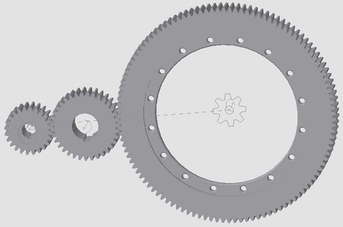
In the coordinate system, the vector function of the cutting cone formed by the tool straight line and its unit normal vector can be expressed in a certain form (equations are omitted here for simplicity). By rotating and to the coordinate system, the tooth surface equation of the small gear in the coordinate system and its unit normal vector can be obtained, along with the meshing equation [16]. Figure 2 shows the 3D model and physical diagram of the small wheel.
2.2 Consideration of Machine Tool Adjustment Parameter Errors
In actual machining, only the tooth surface of the small wheel is usually corrected. Therefore, this article mainly focuses on the machine tool adjustment parameter errors during the small wheel machining process. The relationship between the actual machine tool adjustment parameter , the theoretical machine tool adjustment parameter , and the machine tool adjustment parameter error is expressed as . Substituting this into the tooth surface equation, we can obtain the tooth surface equation containing machine tool parameter errors.
3. TCA Mathematical Model
3.1 Large Wheel Tooth Surface Equation
According to the hypoid gear machining principle, the large wheel is processed by the form – cutting method, and its theoretical tooth surface is determined by literature [15]. The tooth surface equation of the large wheel is expressed as .
3.2 Meshing Coordinate System and Meshing Equations
The meshing coordinate system of the gear pair is shown in Figure 3. There are several coordinate systems, such as , , , and . After the large and small wheels are assembled, they need to rotate a certain angle to reach the meshing position. and are the rotation angles of the small and large wheels, respectively.
The tooth surface equations , and the tooth surface normal vectors , of the small and large wheels in the assembly coordinate system can be obtained through coordinate transformation. According to the gear meshing principle, , , , and satisfy a set of equations. By solving these equations, a series of tooth surface parameters can be obtained. Substituting these parameters into the large wheel tooth surface equation, the contact trajectory line on the large wheel tooth surface can be obtained. Based on this, the contact area on the large wheel tooth surface can be calculated according to the curvature relationship between conjugate tooth surfaces, and the transmission error curve can be obtained according to the definition of transmission error.
4. Influence of Machine Tool Adjustment Parameters on Contact Trajectory and Transmission Error
4.1 Specific Parameters of Hypoid Gear Pairs
The specific blank parameters and machining parameters of the hypoid gear pair are shown in Table 1 and Table 2. These parameters are used as the basis for subsequent analysis of the influence of machine tool adjustment parameters.
| Parameter | Small Wheel | Large Wheel |
|---|---|---|
| Number of Teeth | 7 | 43 |
| Outer End Diameter of Pitch Cone /mm | 150.1349 | 150.3843 |
| Average Pressure Angle / (°) | – | – |
| Offset Distance /mm | – | – |
| Tooth Width /mm | 43.7299 | 40 |
| Shaft Intersection Angle / (°) | – | – |
| Helix Angle / (°) | 45 | 33.45 |
| Face Cone Angle / (°) | 11 | 78.46 |
| Pitch Cone Angle / (°) | 14.44 | 79.21 |
| Root Cone Angle / (°) | 10.26 | 75 |
| Hand of Helix | Left | Right |
Table 1: Basic Parameters of Hypoid Gear Blanks
| Parameter | Small Wheel | Large Wheel |
|---|---|---|
| Cutter Tooth Profile Angle / (°) | 20 | 30 |
| Tool Tip Radius /mm | 114.8409 | 116.1 |
| Vertical Wheel Position /mm | 27.3700 | 111.0757 |
| Radial Wheel Position /mm | 117.1353 | 0 |
| Axial Wheel Position /mm | 0.0730 | 9.6518 |
| Angular Cutter Position / (°) | 65.6224 | 0 |
| Cutter Inclination Angle / (°) | 16.3882 | 0 |
| Cutter Rotation Angle / (°) | – 25.6862 | 0 |
| Blank Installation Angle / (°) | – 6.4576 | 70.2509 |
| Rolling Ratio | 6.0615 | 0 |
| Bed Position /mm | 14.6514 | 0 |
| Helical Motion Coefficient / (mm · rad⁻¹) | 7.1860 | 0 |
Table 2: Machine Tool Machining Adjustment Parameters of Hypoid Gears
4.2 Analysis of Displacement – Type Machine Tool Adjustment Parameter Errors
Displacement – type machine tool adjustment parameters include vertical wheel position, bed position, axial wheel position, and radial cutter position. By using MATLAB to calculate according to the relevant equations and analyzing the obtained results (as shown in Figure 4 and Table 3), the following rules can be found:
- The positive change of the vertical wheel position causes the contact trajectory of the working tooth surface to move towards the large end of the tooth surface, and vice versa for the non – working tooth surface, and the change trends of the two are opposite.
- The positive change of the axial wheel position causes the contact trajectories of the two tooth surfaces of the large wheel to move towards the large end of the tooth surface, and vice versa.
- The positive change of the bed position causes the contact trajectories of the two tooth surfaces of the large wheel to move towards the small end of the tooth surface, and vice versa.
- The positive change of the radial cutter position on the working surface causes the contact trajectory to move towards the small end of the tooth surface, while on the non – working surface, it causes the contact trajectory to move towards the large end and the tooth tip. Excessive radial cutter position error may lead to edge contact at the tooth tip and root.
- The influence of the change of vertical wheel position, bed position, and radial wheel position on the contact trajectory of the working surface is greater than that on the non – working surface, while the opposite is true for the axial wheel position. The influence of the change of vertical wheel position, bed position, and radial wheel position on the transmission error value of the working surface is less than that on the non – working surface, and the opposite is true for the axial wheel position.
- Displacement – type machine tool adjustment parameters mainly affect the tooth – length direction of the contact trajectory. The order of influence degree on the contact trajectory is: radial cutter position > vertical wheel position > bed position > axial wheel position. The order of influence degree on the transmission error value is: radial cutter position > bed position > axial wheel position > vertical wheel position.
| Change Factor | Error Value / ((°) · mm⁻¹) | Working Surface TE Value / μrad | Non – Working Surface TE Value / μrad | Working Surface Deviation /% | Non – Working Surface Deviation /% |
|---|---|---|---|---|---|
| Original Conditions | 0 | – 12.0 | – 12.5 | – | – |
| Tooth Profile Angle | +0.1 | – 11.9 | – 7.3 | 0.83 | 41.6 |
| -0.1 | – 10.8 | – 14.3 | 10 | 14.4 | |
| Cutter Inclination Angle | +0.1 | – 12.04 | – 15.35 | 0.33 | 22.8 |
| -0.1 | – 11.22 | – 9.1 | 6.5 | 27.2 | |
| Vertical Wheel Position | +0.1 | – 12.05 | – 12.42 | 0.42 | 0.64 |
| -0.1 | – 11.96 | – 12.54 | 0.33 | 0.32 | |
| Bed Position | +0.1 | – 11.93 | – 11.88 | 0.58 | 4.96 |
| -0.1 | – 12.012 | – 12.91 | 0.10 | 3.28 | |
| Cutter Rotation Angle | +0.1 | – 11.48 | – 12.9 | 4.33 | 3.2 |
| -0.1 | – 12.24 | – 12.3 | 2.0 | 1.6 | |
| Angular Cutter Position | +0.1 | – 12.0 | – 12.0 | 0 | 0 |
| -0.1 | – 12.0 | – 12.0 | 0 | 0 | |
| Axial Wheel Position | +0.1 | – 12.13 | – 12.34 | 1.08 | 1.28 |
| -0.1 | – 11.86 | – 12.5 | 1.20 | 0 | |
| Radial Cutter Position | +0.1 | – 11.99 | – 9.55 | 0.08 | 23.6 |
| -0.1 | – 10.55 | – 14.3 | 12.08 | 14.4 | |
| Installation Angle | +0.1 | – | – 11.0 | – | 12 |
| -0.1 | – 11.655 | – 13.2 | 2.88 | 5.6 |
Table 3: Influence of Each Parameter on the Transmission Error Value
4.3 Analysis of Angle – Type Machine Tool Adjustment Parameter Errors
Angle – type machine tool adjustment parameters include tooth profile angle, cutter inclination angle, cutter rotation angle, angular cutter position, and blank installation angle. By analyzing the results (as shown in Figure 5 and Table 3), the following conclusions can be drawn:
- The change of the angular cutter position has almost no effect on the tooth surface contact trajectory and the transmission error value at the meshing turning point.
- The change of the tooth profile angle mainly affects the tooth – height direction of the contact area. The positive change of the tooth profile angle of the working surface causes the contact trajectory to move towards the small end and the tooth tip, and vice versa for the non – working surface. Excessive tooth profile angle error may lead to edge contact at the tooth tip and root.
- The change of the cutter inclination angle mainly affects the tooth – length direction of the contact area. The positive change of the cutter inclination angle causes the contact trajectories of the two tooth surfaces of the large wheel to move towards the large end, and vice versa.
- The change of the cutter rotation angle mainly affects the tooth – length direction of the contact area. The positive change of the cutter rotation angle of the working surface causes the contact trajectory to move towards the small end, and the change of the non – working surface causes the contact trajectory to move along the small end.
- The change of the working surface installation angle mainly affects the tooth – height direction of the contact area, while the change of the non – working surface installation angle affects both the tooth – height and tooth – length directions. The positive change of the installation angle causes the contact trajectories of the two tooth surfaces of the large wheel to move towards the large end and the tooth root, and vice versa. Excessive installation angle error may lead to edge contact at the tooth tip and root.
- The influence of the change of tooth profile angle, cutter inclination angle, and installation angle on the contact trajectory of the working surface is greater than that on the non – working surface, while the opposite is true for the cutter rotation angle. The influence of the change of tooth profile angle, cutter inclination angle, and installation angle on the transmission error value of the working surface is less than that on the non – working surface, and the opposite is true for the cutter rotation angle.
- Angle – type machine tool adjustment parameters mainly affect the tooth – length and tooth – height directions of the contact trajectory. The order of influence degree on the contact trajectory is: installation angle > tooth profile angle > cutter inclination angle > cutter rotation angle > angular cutter position. The order of influence degree on the transmission error value is: tooth profile angle > cutter inclination angle > installation angle > cutter rotation angle > angular cutter position.
5. Influence of Machine Tool Adjustment Parameters on Tooth Profile
5.1 Construction of Tooth Mismatch Diagram
To study the influence of machine tool adjustment parameters on the tooth profile, a tooth mismatch diagram is constructed. According to the method in literature [15], the position vectors and unit normal vectors of the grid points on the reference tooth surface and the analyzed tooth surface are calculated. After overlapping the mid – points of the grids of the two tooth surfaces, the projection of the vector of the analyzed surface on the reference tooth surface is calculated, and the projection distance corresponding to each grid point of the tooth surface is defined as the mismatch amount of the tooth surface, expressed as , where , are the position vector and unit normal vector of each grid point of the reference tooth surface, is the position vector of each grid of the analyzed surface, and is the mismatch amount between different tooth surface grid points, and the grid division point serial number ranges from 1 to 45.
5.2 Influence Analysis
- The change of the tooth profile angle mainly affects the pressure angle of the working surface, thus influencing the position of the contact area in the tooth – height direction. For the non – working surface, it also affects the pressure angle, as well as the helix angle and the position of the contact area in the tooth – length direction.
- The change of the radial cutter position mainly affects the helix angle of the working surface, and then influences the position of the contact area in the tooth – length direction. For the non – working surface, it mainly affects the helix angle, and also has an impact on the pressure angle and the position of the contact area in the tooth – height direction.
- The change of the installation angle mainly affects the pressure angle of the working surface, thereby influencing the position of the contact area in the tooth – height direction. For the non – working surface, it affects both the helix angle and the pressure angle, and influences the position of the contact area in both the tooth – length and tooth – height directions. The influence of the installation angle on the non – working surface is greater than that on the working surface.
- The mismatch amount at the large end of the tooth surface is greater than that at the small end. The influence of the radial cutter position on the tooth profile is much larger than that of the tooth profile angle and the installation angle. The positive and negative changes of the tooth profile angle, radial cutter position, and installation angle have a symmetric influence on the tooth profile.
- The influence of the tooth profile angle, radial cutter position, and installation angle on the tooth profile is consistent with their influence on the change of the contact trajectory.
6. Conclusions
In this article, a mathematical machining model for hypoid gears and a tooth contact analysis mathematical model for both the large and small wheels have been established. The impacts of 9 machine tool adjustment parameters on the contact trajectory and transmission error curves of hypoid gears have been analyzed. Additionally, by constructing a tooth mismatch diagram, the influence of machine tool adjustment parameters on the tooth profile has been expounded. The research findings provide a theoretical basis for adjusting the processing parameters of hypoid gears and optimizing the tooth surface contact area. However, factors such as material properties and heat treatment processes have not been considered in this study. Future research will focus on exploring their impacts on the meshing performance of hypoid gears to further improve the understanding and application of hypoid gears in mechanical systems.
7. Future Research Directions
7.1 Incorporating Material – related Factors
Material properties play a crucial role in the performance of hypoid gears. Different materials have different mechanical properties, such as hardness, toughness, and fatigue strength. These properties can affect the wear resistance, load – carrying capacity, and service life of hypoid gears. Future research could focus on establishing models that incorporate material properties into the analysis of meshing performance. For example, by using finite element analysis methods, the stress and strain distributions on the tooth surfaces of hypoid gears made of different materials can be simulated under various loading conditions. This would help in understanding how material – related factors interact with machine tool adjustment parameters to influence the overall performance of the gear pair.
7.2 Considering Heat Treatment Processes
Heat treatment processes can significantly change the microstructure and mechanical properties of hypoid gears. Processes like quenching and tempering can improve the hardness and strength of the gear material, while also affecting its internal stress state. Research should be conducted to study how different heat treatment processes impact the meshing performance of hypoid gears. This could involve experimental investigations where gears are heat – treated under different conditions and then tested for their meshing characteristics, such as contact stress, transmission error, and noise levels. The results could be used to optimize the heat treatment processes in combination with appropriate machine tool adjustment parameters to achieve better – performing hypoid gears.
7.3 Multi – objective Optimization
In real – world applications, multiple performance criteria need to be considered simultaneously when designing hypoid gears. These criteria may include minimizing transmission error, reducing noise, maximizing load – carrying capacity, and improving wear resistance. Future research could focus on developing multi – objective optimization algorithms that take into account all these criteria along with the machine tool adjustment parameters. By using advanced optimization techniques such as genetic algorithms or particle swarm optimization, the optimal combination of machine tool adjustment parameters and gear design parameters can be determined to meet the complex requirements of different mechanical systems.
7.4 Experimental Validation
Although theoretical models and numerical simulations are important tools for understanding the behavior of hypoid gears, experimental validation is essential to ensure the accuracy and reliability of the research findings. Future studies should include more comprehensive experimental setups to measure the actual contact trajectories, transmission errors, and tooth profiles of hypoid gears under different machining and operating conditions. The experimental data can be used to validate and refine the existing mathematical models, and also to provide practical insights into the manufacturing and operation of hypoid gears.
8. Industrial Applications and Significance
8.1 Automotive Industry
In the automotive industry, hypoid gears are widely used in differential mechanisms and drive axles. The optimized meshing performance of hypoid gears, achieved through proper adjustment of machine tool parameters, can lead to several benefits. For example, reduced transmission error can result in smoother power transfer, improving the driving comfort of vehicles. Lower noise levels are also highly desirable, especially in modern electric and hybrid vehicles where the absence of engine noise makes gear noise more noticeable. Additionally, enhanced load – carrying capacity can improve the durability of the drive system, reducing maintenance costs and extending the service life of the vehicle.
8.2 Aerospace Industry
In aerospace applications, hypoid gears are used in various mechanical systems, such as aircraft landing gear and helicopter transmission systems. The stringent requirements of the aerospace industry, including high reliability, lightweight design, and high – speed operation, make the optimization of hypoid gear meshing performance crucial. By precisely controlling the machine tool adjustment parameters, gears with better meshing characteristics can be produced. This can help in reducing the weight of the gear system without sacrificing its performance, which is essential for improving the fuel efficiency and overall performance of aircraft and helicopters.
8.3 Heavy – Machinery Industry
In heavy – machinery, such as construction equipment and mining machinery, hypoid gears are subjected to large loads and harsh operating conditions. Understanding the influence of machine tool adjustment parameters on meshing performance can enable manufacturers to produce gears with higher load – carrying capacity and better wear resistance. This can significantly improve the reliability and productivity of heavy – machinery, reducing downtime and maintenance costs in industries where continuous operation is critical.
9. Comparison with Other Gear Types
9.1 Spur Gears
Spur gears are the simplest type of gears, with straight teeth parallel to the axis of rotation. Compared to hypoid gears, spur gears have a relatively simple manufacturing process and lower cost. However, they are mainly used for transmitting motion between parallel shafts and have limitations in terms of load – carrying capacity and smoothness of transmission. Hypoid gears, on the other hand, can transmit motion between non – parallel and non – intersecting shafts, and offer higher load – carrying capacity and smoother operation due to their helical – tooth design and offset axis. The complex relationship between machine tool adjustment parameters and meshing performance in hypoid gears is a trade – off for their superior functionality in more demanding applications.
9.2 Helical Gears
Helical gears also have helical – shaped teeth, which provide better meshing characteristics compared to spur gears. They can transmit motion between parallel shafts with less noise and vibration. However, hypoid gears have a more complex geometry due to their offset axis, which allows for more compact designs in some applications. The adjustment of machine tool parameters for hypoid gears is more complex than for helical gears because of the additional degrees of freedom in their manufacturing process. But this complexity also enables hypoid gears to be used in a wider range of applications, especially those that require non – parallel shaft arrangements.
9.3 Bevel Gears
Bevel gears are used to transmit motion between intersecting shafts. Hypoid gears are a special type of bevel gears with an offset axis. The offset in hypoid gears allows for a larger contact ratio and more gradual tooth engagement, resulting in smoother transmission and higher load – carrying capacity compared to standard bevel gears. The machine tool adjustment parameters for hypoid gears are more numerous and have a more intricate influence on meshing performance due to the additional offset factor, which needs to be carefully controlled during the manufacturing process to achieve the desired gear performance.
10. Challenges in Research and Manufacturing
10.1 Complexity of Mathematical Models
The mathematical models used to analyze hypoid gear meshing performance, especially those considering machine tool adjustment parameters, are quite complex. These models involve multiple variables, coordinate transformations, and non – linear equations. Solving these models accurately requires advanced numerical methods and high – performance computing resources. Moreover, the accuracy of the models depends on the accuracy of the input parameters, such as the measurement of gear geometry and machine tool settings. Any errors in these input parameters can lead to significant deviations in the predicted meshing performance.
10.2 Manufacturing Tolerances
In the manufacturing process of hypoid gears, maintaining tight manufacturing tolerances is a major challenge. The complex geometry of hypoid gears makes it difficult to achieve high – precision machining. Small errors in machine tool adjustment parameters during manufacturing can accumulate and result in significant deviations in the final gear geometry. These deviations can have a detrimental effect on the meshing performance of the gear pair, such as increased transmission error and noise. Ensuring consistent and accurate manufacturing tolerances requires advanced machining technologies and strict quality control measures.
10.3 Lack of Comprehensive Experimental Data
There is a lack of comprehensive experimental data on the meshing performance of hypoid gears under different operating conditions and with various machine tool adjustment parameters. Experimental studies are time – consuming and expensive, and it is difficult to cover all possible parameter combinations. Without sufficient experimental data, it is challenging to validate and improve the existing mathematical models. This also limits the development of more accurate prediction methods for hypoid gear meshing performance.
11. Strategies for Overcoming Challenges
11.1 Simplification and Optimization of Mathematical Models
To address the complexity of mathematical models, researchers can focus on simplifying and optimizing them. This can involve using approximation methods and reducing the number of variables without sacrificing too much accuracy. For example, some less – significant factors can be neglected in the initial stages of analysis to simplify the model and make it more computationally efficient. Additionally, advanced numerical algorithms can be developed to improve the convergence speed and accuracy of solving the complex equations in the models.
11.2 Advanced Manufacturing Technologies
Investing in advanced manufacturing technologies can help in achieving tighter manufacturing tolerances. Technologies such as five – axis machining centers with high – precision control systems can enable more accurate machining of hypoid gears. Additionally, the use of in – process measurement and compensation techniques can help in detecting and correcting machining errors in real – time. This can significantly improve the quality of hypoid gears and reduce the impact of manufacturing tolerances on meshing performance.
11.3 Collaborative Research for Experimental Data Collection
To overcome the lack of experimental data, collaborative research efforts can be encouraged. Multiple research institutions and industrial partners can work together to conduct comprehensive experimental studies on hypoid gear meshing performance. By sharing resources and data, a larger database of experimental results can be established. This data can be used to validate and improve the existing mathematical models, and also to develop new prediction methods based on empirical data.
12. Conclusion and Outlook
In conclusion, the study of the influence of machine tool adjustment parameters on the meshing performance of hypoid gears is a complex but essential area of research. Through the establishment of mathematical models and in – depth analysis, significant progress has been made in understanding this relationship. However, there are still many challenges to be overcome, such as the complexity of models, manufacturing tolerances, and the lack of experimental data.
Looking ahead, future research should focus on integrating more factors into the analysis, such as material properties and heat treatment processes, and developing multi – objective optimization methods. At the same time, continuous efforts should be made to improve manufacturing technologies and experimental techniques to enhance the accuracy and reliability of hypoid gear manufacturing. With these advancements, hypoid gears will be able to meet the increasingly demanding requirements of modern mechanical systems in various industries, contributing to the development of more efficient, reliable, and quiet mechanical devices.