
It can be seen from the analysis that the two-axis linkage cutting machining of spiral bevel gear is mainly composed of the following two parts: ① the two-axis linkage motion in the cutting machining process of spiral bevel gear and ② the feed motion in the direction of tooth height. In the process of spiral bevel gear cutting, the movement of the blade relative to the tooth blank in the x-axis direction can be implemented through the following scheme: in the process of spiral bevel gear cutting, the point milling blade rotates at high speed but does not move, while the tooth blank moves relative to the blade in the X-axis direction. Then the linkage motion required in the two-axis linkage cutting process of spiral bevel gear is realized by controlling the motion of gear blank, so that the motion of spiral bevel gear cutting can be controlled centrally. Combined with the analysis of the implementation scheme of three-axis linkage gear cutting motion of spiral bevel gear, the motion scheme of two-axis linkage is shown in Figure (the blade takes the common finger milling cutter as an example). The tooth blank base cone in the figure is tangent to the auxiliary plane – (q) plane, the apex of the base cone coincides with the geometric center of the (q) plane at point O, and the end plane of the finger milling cutter is located in the (q) plane. In the actual machining process, the (q) plane is located in the horizontal plane, and the axis line of the gear blank is inclined by a base cone angle relative to the horizontal plane—— δ b。
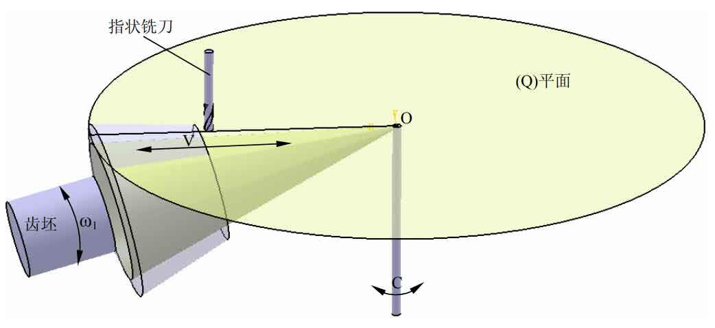
In the process of cutting the tooth surface of spiral bevel gear, the movement V of gear blank in the x-axis direction and the rotation around its own rotation axis are controlled ω 1 to realize the two-axis linkage movement required for spiral bevel gear cutting, in which the cutting point of the blade is located on the x-axis, and the motion relationship between the two must meet the formula for different tooth surface machining. In the process of spiral bevel gear cutting, the feed movement in the tooth height direction is realized by controlling the rotation movement of the gear blank around the vertical axis passing through the apex of the cone, that is, the rotation movement of axis C in the control diagram.