
According to Hertz contact theory, the elastic deformation of tooth surface increases with the increase of contact stress when the tooth surface is subjected to normal contact force. The change of contact stress is the main reason for the elliptical mark on the tooth surface of hypoid gear. Therefore, the elastic deformation of tooth surface can be connected with the clearance around the contact point. When the tooth surface clearance is very small, the instantaneous contact ellipse can be described by the area with the same tooth surface clearance on the tooth surface in a certain meshing state. The detailed steps to solve the instantaneous contact ellipse and tooth surface contact impression are as follows:
Step 1: set the contact point of the two tooth surfaces as P, take the normal direction of the contact point as the Z axis, and establish a rectangular coordinate system for any two mutually perpendicular axes on the contact tangent plane M. the plane n passes through the Z axis and is perpendicular to the contact tangent plane M. There are two tracks at the intersection of plane n and two gear faces, and the distance between the two tracks along the z-axis direction is the tooth surface clearance. Two boundary points of the instantaneous contact ellipse on the straight line are obtained by searching along any direction and the opposite direction from the instantaneous contact point. Then, the point on the instantaneous contact ellipse where the clearance between the tooth surfaces ∑ 1 and ∑ 2 is equal to the elastic deformation is the boundary point on the instantaneous contact ellipse.
Step 2: for a given tooth clearance, the corresponding contact ellipse must be a closed curve around the contact center. Only by rotating the plane n around the z-axis U3 at a certain angle interval, two real contact ellipses on the two tooth surfaces at the current moment can be found. The major axis of the contact ellipse must pass through the two points on the boundary of the contact ellipse farthest from the contact center; on the contrary, the minor axis must pass through the two boundary points which are the shortest from the contact center.
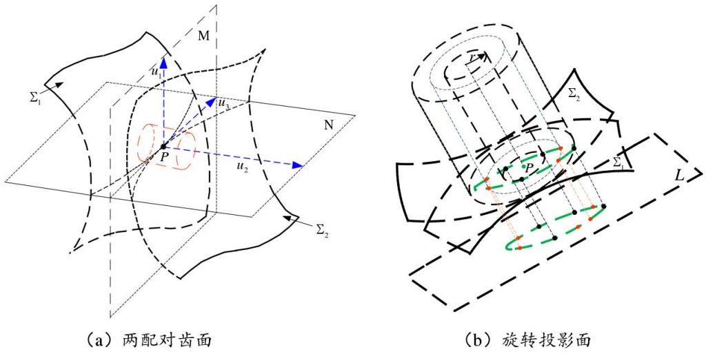
Step 3: repeat the above steps at each meshing position in the whole gear meshing cycle to search the contact marks composed of all ellipse boundary points, as shown in Fig (b) It is shown that the part of the area enclosed by these contact ellipses within the effective contact boundary of the tooth surface constitutes the contact mark of the whole tooth surface, which can be used to simulate the gear rolling inspection mark in the design stage, as an effective reference for the design of gear meshing performance.
This method does not need complex curvature calculation, but it can not get the accurate contact ellipse boundary, the contact ellipse long axis and short axis, as well as the real contact impression.
Although this method avoids complicated calculation, it still can’t get the accurate major and minor axis of the instantaneous contact ellipse (although the instantaneous contact line may not be a straight line, it is still the long axis of the ellipse for the convenience of comparison below), and the obtained instantaneous contact ellipse can not reflect the contact situation of each instantaneous tooth surface meshing.