
In my extensive research on heat treatment processes for critical automotive components, I have focused on the spiral bevel gear, a fundamental element in vehicle differential systems. The performance and longevity of these gears are heavily dependent on their surface properties, which are predominantly achieved through carburizing and quenching treatments. During my investigations, I identified that the flow velocity of the quenching medium within the quenching tank is a critical, yet often underexplored, parameter that significantly influences the final microstructure, hardness, residual stress state, and ultimately, the service life of the spiral bevel gear. This article presents a detailed account of my methodology, which integrates computational fluid dynamics (CFD) with multi-physics finite element analysis (FEA) to unravel the complex interdependencies between quenchant flow, heat transfer, phase transformations, and mechanical responses in a spiral bevel gear.
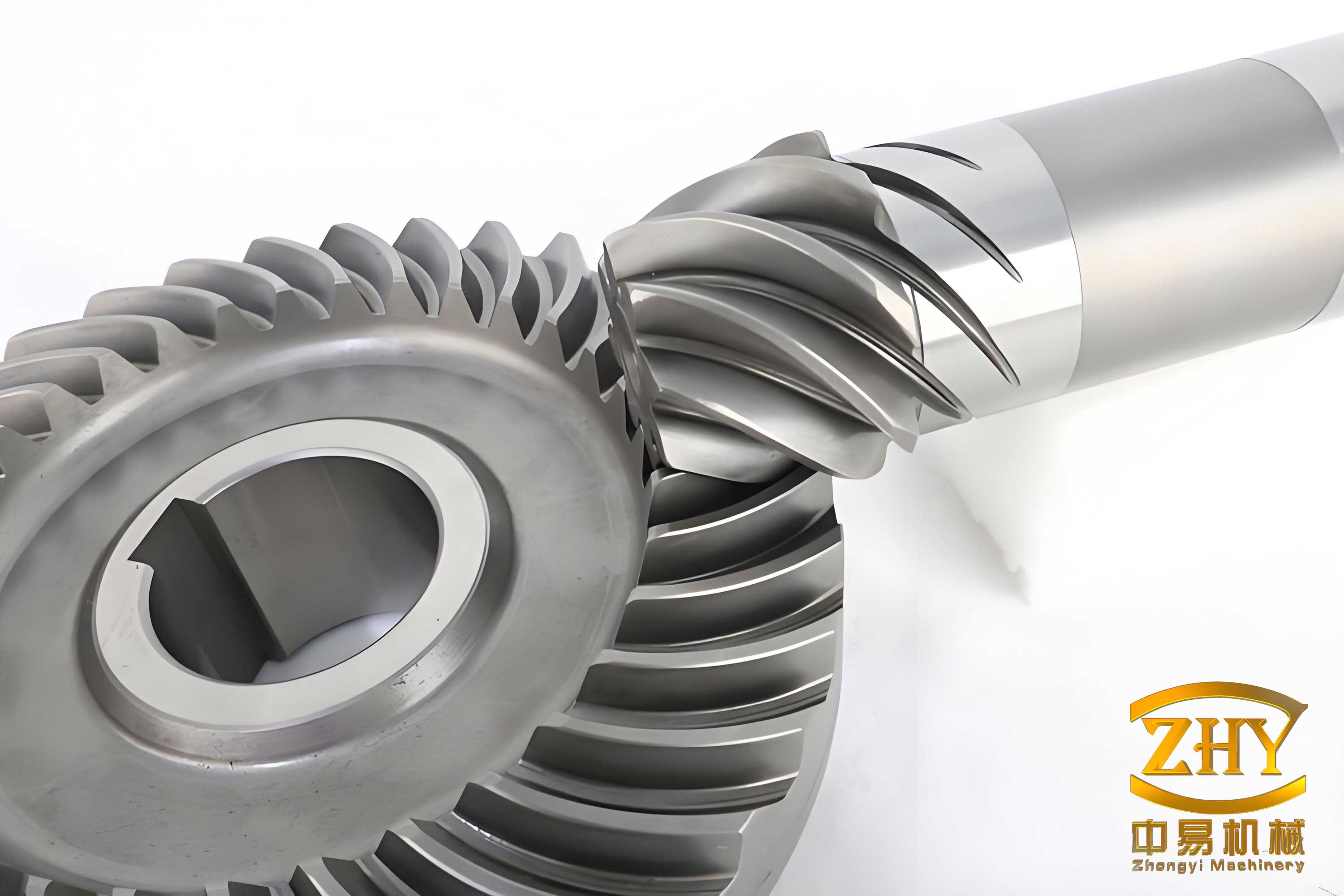
The core challenge in optimizing the quenching process for a complex geometry like the spiral bevel gear lies in accurately characterizing the non-uniform heat extraction from its various surfaces—the tooth flanks, the inner bore, the outer rim, and the bottom face. Traditional simulations often assume a constant or averaged heat transfer coefficient (HTC), neglecting the localized effects of fluid flow. In my work, I prioritized the development of a more realistic boundary condition model. I commenced by constructing a full-scale model of an industrial quenching tank equipped with an agitator. Using ANSYS CFX, a dedicated fluid dynamics software, I simulated the three-dimensional, turbulent flow field of ISO-N32 quenching oil for various agitator speeds, corresponding to different inlet flow velocities. The spiral bevel gear was positioned on a fixture within this domain. The CFD simulations provided detailed maps of the oil velocity over every surface of the spiral bevel gear. A critical finding was the substantial variation in average surface velocity across different regions of the gear for a given global inlet condition, as summarized in Table 1.
| Inlet Velocity (m/s) | Tooth Flank (m/s) | Bottom Face (m/s) | Inner Bore (m/s) | Outer Rim (m/s) |
|---|---|---|---|---|
| 0.5 | 0.117 | 0.050 | 0.156 | 0.076 |
| 1.0 | 0.237 | 0.126 | 0.320 | 0.212 |
| 1.5 | 0.429 | 0.196 | 0.567 | 0.399 |
| 2.0 | 0.590 | 0.223 | 0.708 | 0.602 |
These surface velocity values were indispensable. I correlated them with experimentally derived HTC curves for the same oil under controlled flow conditions. The HTC is not a material constant but a function of surface temperature and local fluid velocity. For each surface region of the spiral bevel gear, I assigned a specific HTC vs. temperature curve corresponding to its calculated average velocity range. This approach fundamentally differentiated my simulation from standard practices and allowed for a spatially resolved thermal boundary condition during the quenching stage.
The subsequent thermomechanical-metallurgical analysis was performed using DEFORM-HT, a software capable of coupled diffusion, phase transformation, and stress analysis. I modeled the spiral bevel gear made from AISI 8620/20CrMoH steel. The complete heat treatment cycle was simulated: heating to austenitization, carburizing (with boost and diffuse stages), temperature equalization, and finally, quenching in the agitated oil. The carbon diffusion during carburizing was governed by Fick’s second law, modified to account for temperature and pressure effects on solubility:
$$ \frac{\partial C}{\partial t} = \nabla \cdot (D(T, C) \nabla C) $$
where \( C \) is the carbon concentration, \( t \) is time, and \( D \) is the temperature and composition-dependent diffusivity. The boundary condition at the surface was a prescribed carbon flux related to the atmosphere potential. This model successfully predicted a case depth of approximately 1.1 mm with a uniform surface carbon content near 0.8 wt.% for the tooth flank of the spiral bevel gear.
The quenching simulation incorporated temperature-dependent material properties, latent heat of phase transformations, and transformation-induced plasticity (TRIP). The heat conduction equation solved was:
$$ \rho C_p \frac{\partial T}{\partial t} = \nabla \cdot (k \nabla T) + \dot{Q}_{latent} $$
where \( \rho \) is density, \( C_p \) is specific heat, \( k \) is thermal conductivity, and \( \dot{Q}_{latent} \) is the heat generation rate due to phase changes (austenite to ferrite, pearlite, bainite, and martensite). The phase transformation kinetics for diffusional transformations were modeled using the Johnson-Mehl-Avrami-Kolmogorov (JMAK) equation, while the martensitic transformation was modeled using the Koistinen-Marburger relationship:
$$ f_M = 1 – \exp[-\alpha (M_s – T)] $$
where \( f_M \) is the martensite volume fraction, \( \alpha \) is a material constant, and \( M_s \) is the martensite start temperature, which itself is a function of carbon content. The stress-strain response was calculated using an thermo-elasto-plastic constitutive model with strain components from thermal, phase transformation, and plasticity contributions:
$$ d\varepsilon_{total} = d\varepsilon_{elastic} + d\varepsilon_{plastic} + d\varepsilon_{thermal} + d\varepsilon_{transformation} $$
The results from this integrated model were profound. The cooling curves for different locations on the spiral bevel gear varied dramatically with inlet flow velocity. For a low inlet velocity of 0.5 m/s, geometry dominated cooling, with the thin tooth flanks cooling fastest. As velocity increased, the influence of forced convection grew. The tooth flank, experiencing the highest local velocities, showed a monotonic increase in cooling rate with inlet speed. However, for the inner bore and outer rim, the cooling rate peaked at an intermediate inlet velocity of 1.5 m/s. At 2.0 m/s, the flow in these regions became so turbulent that it possibly led to a slight reduction in effective heat transfer or earlier vapor film collapse, slightly reducing the cooling rate. The bottom face, with generally lower velocities, showed a continuous but modest increase in cooling rate.
These thermal histories directly dictated the final microstructure and hardness of the spiral bevel gear. Martensite, the desired hard phase, forms when the cooling rate exceeds a critical value. My simulations tracked the martensite volume fraction evolution in real-time. The final surface martensite content and hardness for the spiral bevel gear under different quenching conditions are consolidated in Table 2. The data clearly shows that maximizing hardness on all surfaces of a spiral bevel gear requires a nuanced approach; a single high flow rate is not optimal for every region.
| Region / Inlet Velocity | 0.5 m/s | 1.0 m/s | 1.5 m/s | 2.0 m/s |
|---|---|---|---|---|
| Tooth Flank | Martensite Fraction / Hardness (HRC) | |||
| 0.75 / 55.2 | 0.82 / 58.7 | 0.89 / 63.2 | 0.92 / 64.6 | |
| Inner Bore | 0.56 / 47.2 | 0.65 / 51.4 | 0.78 / 56.9 | 0.72 / 53.7 |
| Outer Rim | 0.71 / 53.5 | 0.76 / 55.3 | 0.82 / 58.7 | 0.78 / 57.4 |
| Bottom Face | 0.32 / 40.7 | 0.34 / 42.8 | 0.32 / 41.5 | 0.46 / 45.4 |
| Gear Core | 0.40 / 32.8 | 0.43 / 36.3 | 0.47 / 40.2 | 0.51 / 43.5 |
The evolution of residual stress is another critical performance metric for a spiral bevel gear, affecting fatigue resistance and dimensional stability. My stress analysis revealed a complex temporal sequence. Initially, during rapid surface cooling, the surface contracts more than the hot core, inducing tensile stresses on the surface and compressive stresses in the core. As the core later cools and contracts, and as the surface undergoes martensitic expansion, this stress state reverses. The final residual stress state typically consists of beneficial compressive stresses on the surface and tensile stresses in the core. The magnitude of these stresses, however, was sensitive to local cooling intensity. Regions with higher effective HTC, like the tooth flank at high flow, underwent more severe thermal gradients and phase transformation strains, resulting in higher final compressive residual stresses (exceeding 500 MPa at 2.0 m/s inlet velocity). The stress state in slower-cooling regions like the bottom face was much lower in magnitude. Interestingly, while the flow velocity significantly affected the stress magnitude, the fundamental pattern of surface compression and core tension remained consistent across all cases for the spiral bevel gear.
To validate the predictive capability of my model, I compared its outputs against physical experimental data from a similarly processed spiral bevel gear. The simulation predicted a tooth flank hardness of approximately 60.3 HRC and a core hardness of 37.1 HRC after quenching and tempering. Physical measurements on an actual gear yielded 59.2 HRC and 36.9 HRC, respectively, demonstrating excellent agreement. Furthermore, the predicted microstructure gradients—a high-carbon martensitic case with some retained austenite and a lower-carbon, tougher core—matched the observations from scanning electron microscopy of sectioned samples.
In conclusion, my integrated numerical study underscores that the quenching medium flow velocity is a powerful lever for controlling the properties of a carburized and quenched spiral bevel gear. A one-size-fits-all high flow rate is not optimal. Instead, the design of the quenching tank agitation system should aim to produce a flow field that delivers tailored cooling intensities to different regions of the complex spiral bevel gear geometry. For the specific gear and tank studied, an inlet velocity around 1.5 m/s promoted the most favorable balance of high hardness on the critical tooth flanks, inner bore, and outer rim, while a slightly higher velocity might be targeted if the bottom face hardness is a concern. The methodology I developed, linking CFD-derived flow-dependent HTCs to a sophisticated multi-field simulation, provides a robust virtual platform for optimizing heat treatment processes for spiral bevel gears and other complex components, reducing the need for costly and time-consuming physical trial-and-error.