
The transmission of motion and power between intersecting shafts is a fundamental requirement in mechanical systems, finding critical applications in automotive differentials, aerospace actuators, industrial robotics, and heavy machinery. Among the various solutions, bevel gears stand out for their efficiency and compact design. Straight bevel gears, characterized by their simplicity, ease of design, and lower manufacturing cost compared to their spiral or hypoid counterparts, remain indispensable for numerous applications where high speeds are not the primary concern. However, the manufacturing landscape for these components has long been dominated by traditional, discontinuous methods such as shaping (planing), form milling, and broaching. These processes, while capable, suffer from inherent limitations in production efficiency, reliance on operator skill, and sometimes, compromises in achieving the ideal theoretical tooth form. This research gap presents a significant opportunity for innovation. Gear hobbing, a continuous generating process renowned for its high productivity and excellent economy in cylindrical gear production, offers a compelling paradigm shift. This article delves into the foundational research and development of a novel continuous generating method for straight bevel gears, inspired by the principles of gear hobbing. We explore the underlying theory, the design of a specialized conical hob tool, and the virtual validation of the entire process, aiming to demonstrate a viable path towards more efficient and precise manufacturing of straight bevel gears.
The core geometry of a straight bevel gear is intrinsically more complex than that of a spur gear. Its teeth are tapered, converging towards the apex of the pitch cone. Key geometric parameters define its form, primarily referenced at the larger heel end. These include the number of teeth (z), module (m) at the heel, pressure angle (α), shaft angle (Σ, often 90°), face width (B), and pitch cone angle (δ). The tooth form is theoretically a spherical involute, generated by the trace of a point on a plane that rolls without slipping on the base cone. The mathematical definition of this tooth surface is the cornerstone for accurate modeling and subsequent tool design. A coordinate system S(O-x, y, z) is fixed with its origin at the cone apex O. The generation process can be derived, yielding the parametric equations for any point on the involute tooth surface. For a point on the heel-end involute, the coordinates are given by:
$$ x = R[\sin\psi \sin(\phi + \theta) + \cos\psi \cos\theta \cos(\phi + \theta)] $$
$$ y = R[\sin\psi \cos(\phi + \theta) – \cos\psi \cos\theta \sin(\phi + \theta)] $$
$$ z = R\cos\psi \sin\theta $$
where R is the cone distance (generating sphere radius), θ is the base cone angle, ψ is the space angle parameter along the involute, and φ is the roll angle related to ψ by φ = ψ sinθ. For the toe-end (smaller end) or any point along the tooth face width, the cone distance R is adjusted accordingly, and a length parameter l (varying from R-B to R) is introduced. This mathematical description enables the parametric modeling of the gear, which is crucial for generating accurate digital twins for simulation and analysis. A summary of key derived geometric parameters is presented in Table 1.
| Parameter | Calculation Formula |
|---|---|
| Pitch Diameter (d) | d = m * z |
| Addendum (ha) | ha = m * ha* (where ha* is addendum coefficient, typically 1) |
| Dedendum (hf) | hf = m * (ha* + c*) (where c* is clearance coefficient) |
| Cone Distance (R) | R = d / (2 sinδ) |
| Face Width (B) | B ≤ R/3 (common design rule) |
| Addendum Angle (θa) | θa = arctan(ha/R) |
| Dedendum Angle (θf) | θf = arctan(hf/R) |
Conventional manufacturing methods like gear shaping simulate the meshing of a crown gear with the workpiece. The tool reciprocates while the workpiece indexes intermittently, leading to non-cutting return strokes and limiting productivity. Form milling uses a cutter whose profile matches the tooth space but requires individual indexing for each tooth. The quest for a continuous process logically leads to the exploration of gear hobbing. The principle of gear hobbing for cylindrical gears involves a worm-like hob and a workpiece rotating in a precisely synchronized ratio, akin to a screw meshing with a gear. Translating this to bevel gears requires re-conceptualizing the tool-workpiece interaction as the meshing of two conjugate straight bevel gears. In this proposed method, one member of this gear pair is the workpiece, and the other is a specially designed cutting tool—a conical hob. Their rotational axes are set at the prescribed shaft angle. The synchronized rotation between the hob (C1 axis) and the workpiece (C axis) provides the continuous generating motion, enveloping the correct tooth form onto the blank. This is complemented by linear feed motions: a radial infeed (X axis) to achieve the full tooth depth and an axial feed (Z axis) along the workpiece’s face width to complete the gear. The fundamental kinematic relationship is the gear ratio i:
$$ i = \frac{\omega_{\text{workpiece}}}{\omega_{\text{hob}}} = \frac{z_{\text{hob}}}{z_{\text{workpiece}}} $$
The success of this gear hobbing approach hinges entirely on the design and integrity of the conical hob. This tool is not a standard worm hob but a conical gear with cutting edges integrated onto its flanks. Its basic geometry mirrors that of the mating gear in the imaginary pair, with a pitch cone angle complementary to the workpiece’s. However, critical machining features are added: helical gashes (or flutes) are machined along its conical surface to form discrete cutting teeth, a rake face is ground to provide positive cutting angles, and the teeth are relieved (backed off) to create necessary clearance angles. Key design parameters include the gash helix angle (affecting tooth count and smoothness of cut), number of gashes, rake angle (γ), and clearance angles for both the top (αc) and side edges (αs). The hob’s face width must exceed the workpiece’s to ensure complete tooth generation. The structural soundness of this complex tool is paramount. Finite Element Analysis (FEA) is employed to evaluate its performance. Static structural analysis under simulated cutting loads confirms that stress and deformation are within safe limits for the tool material (e.g., high-speed steel or carbide). Modal analysis reveals the tool’s natural frequencies, which are sufficiently high to avoid resonance with typical machine tool excitation frequencies. For instance, the first six natural frequencies might range from ~4 kHz to ~18 kHz, well above operational ranges. Furthermore, dynamic transient analysis of the meshing engagement between the hob and a workpiece gear provides insights into contact stress distribution and variation during the gear hobbing process, validating the smooth transfer of motion and load.
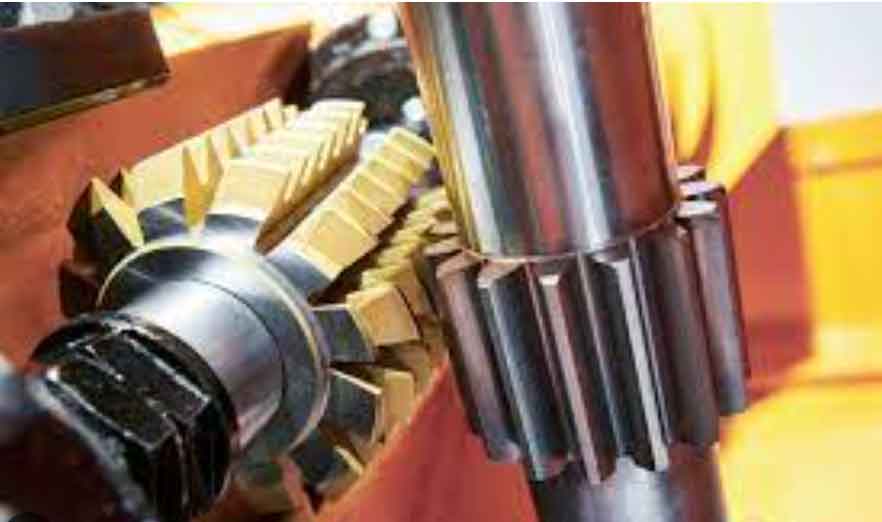
To validate the gear hobbing process without physical prototyping, virtual manufacturing simulation using software like VERICUT is indispensable. This involves constructing a digital twin of the machine tool environment. A 4-axis kinematic model is built, comprising the rotary axes for the hob (C1) and workpiece (C), and the linear axes for radial (X) and axial (Z) motion. The mathematically defined conical hob model is imported as the cutting tool. A cylindrical blank is defined as the stock. The core of the simulation is the NC program, which synchronously commands all four axes to replicate the gear hobbing kinematics. The coordinated motion is governed by coordinate transformation matrices. If we define a tool coordinate system S1 and a workpiece system S4, the position of a hob point in the workpiece system is found by:
$$ \mathbf{P}_4 = \mathbf{T}_3 \cdot \mathbf{T}_2 \cdot \mathbf{T}_1 \cdot \mathbf{P}_1 $$
where T1, T2, T3 are homogeneous transformation matrices representing the rotations and translations of axes C1, X, Z, and C, respectively. The simulation runs this program, and VERICUT’s material removal engine calculates the resulting geometry. The outcome is a digitally machined straight bevel gear. Its validity is checked using the software’s Auto-Diff module, which compares the simulated gear against the perfect CAD model derived from the parametric spherical involute equations. The comparison shows minimal overcut or undercut, with deviations within acceptable tolerance bands, conclusively proving the correctness of the tool geometry and the gear hobbing kinematics. Table 2 summarizes the primary axes involved in this simulated gear hobbing setup.
| Machine Axis | Function in Gear Hobbing Process |
|---|---|
| C1 Axis (Hob Spindle) | Primary cutting rotation of the conical hob. |
| C Axis (Workpiece Spindle) | Synchronized rotation with C1 to provide generating motion. |
| X Axis | Radial infeeding to reach the full tooth depth. |
| Z Axis | Axial feed along the workpiece face width to generate the entire tooth length. |
The exploration of continuous generating methods for straight bevel gears through a gear hobbing-inspired approach presents a significant advancement over traditional intermittent processes. This research establishes a foundational framework encompassing the theoretical tooth geometry, the innovative design and analysis of a conical hob, and the comprehensive virtual validation of the machining process via multi-axis simulation. The results demonstrate that a correctly designed conical hob, engaged in a precisely synchronized kinematic relationship with the workpiece, can successfully generate an accurate spherical involute tooth form on a straight bevel gear blank. The gear hobbing method promises substantial gains in productivity due to its continuous nature, potentially better surface finish from more distributed cutting action, and high flexibility from the generating principle. Future work naturally extends towards the physical realization of the conical hob, experimental gear hobbing trials on a suitable multi-axis platform, and in-depth investigation into the resulting gear quality, surface integrity, and tool life. Furthermore, optimizing hob geometry for different materials, developing dedicated CNC algorithms for efficient toolpath generation, and exploring the potential for hard-finishing applications could be fruitful avenues. In conclusion, the adaptation of gear hobbing principles to straight bevel gear manufacturing holds considerable promise for modernizing the production of these essential mechanical components, offering a compelling blend of efficiency, precision, and economic viability.