
In the field of mechanical transmission systems, bevel gears play a crucial role in applications such as automotive differentials, marine propulsion, and aerospace mechanisms. The performance of bevel gears directly impacts the efficiency and reliability of the entire system, making it essential to study factors that affect their operation. One critical aspect is the misalignment of bevel gears, which refers to the relative displacement between the driving and driven gears under load. This misalignment influences contact patterns, stress distribution, and transmission error, ultimately affecting the fatigue life and safety of bevel gears. However, traditional analyses often overlook the effects of thermal expansion in shaft systems, which can alter system stiffness and, consequently, misalignment. In this article, I will explore how thermal expansion impacts the misalignment of bevel gears, using a detailed nonlinear finite element model that incorporates thermal effects. The goal is to provide insights into how thermal expansion can be leveraged in the design and rating of bevel gears, with a focus on practical implications for engineering applications.
Bevel gears, including spiral bevel gears and hypoid gears, are widely used in power transmission systems where axes intersect. The misalignment of bevel gears arises due to deformations in the transmission system under operational loads. It is typically quantified by components such as axial displacement, offset displacement, and angular displacement, which collectively determine the gear pair’s contact behavior. For instance, in automotive drive axles, bevel gears transmit torque while accommodating slight misalignments caused by shaft deflections. However, as systems operate, friction and heat generation lead to temperature rises, causing thermal expansion in shafts, bearings, and housings. This thermal expansion introduces additional deformations and changes in bearing stiffness, which in turn affect the overall system deformation and misalignment of bevel gears. Despite its significance, this aspect has not been thoroughly investigated in existing literature, prompting the need for a comprehensive analysis.
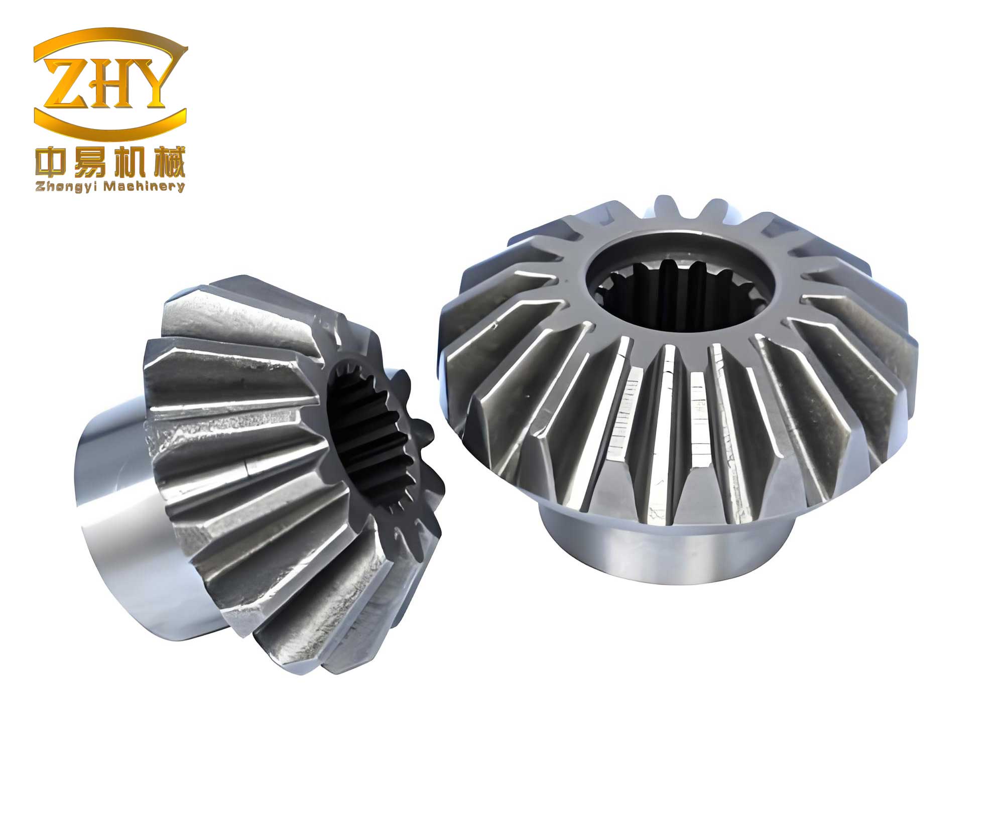
To address this gap, I developed a nonlinear finite element model for a bevel gear transmission system that accounts for thermal expansion effects. The model includes shaft systems supported by bearings, with bevel gears modeled as simplified connections. The stiffness of bearings is nonlinear and coupled across directions, and thermal expansion influences this stiffness through radial interference and axial deformations. By deriving relationships between thermal expansion, bearing stiffness, and system deformation, I can calculate the misalignment of bevel gears under various thermal conditions. This approach allows for a more accurate assessment of bevel gear performance, especially in high-temperature environments where thermal effects are pronounced. In the following sections, I will detail the modeling process, theoretical derivations, and numerical examples to demonstrate the impact of thermal expansion on bevel gears misalignment.
The transmission system considered here is based on a simplified automotive drive axle, consisting of two shafts supported by multiple bearings and a pair of hypoid bevel gears. The shafts are modeled using beam elements that account for shear deformation, while bearings are represented by specialized bearing elements that capture nonlinear stiffness. For bevel gears, a simplified model is used where the gears are connected at the pitch point via an equivalent mesh stiffness matrix. This simplification is valid because bevel gears operate under localized contact conditions, and the overall system deformation is more influenced by shaft and bearing deformations than by detailed tooth geometry. The system’s stiffness equation is expressed as:
$$ \mathbf{P} = \mathbf{K} \delta $$
where \(\mathbf{K}\) is the global stiffness matrix, \(\mathbf{P}\) is the load vector, and \(\delta\) is the displacement vector. The misalignment of bevel gears is computed from the displacements at key points on the shafts, as defined by standard metrics. Specifically, for a bevel gear pair, the misalignment components include axial displacement \(\Delta P\), offset displacement \(\Delta E\), and angular displacement \(\Delta \Sigma\), which are combined into a comprehensive misalignment value used in rating formulas for bevel gears. The relationship between these components and the system displacements is given by:
$$ \Delta P = \Delta P^G + \Delta P^W $$
$$ \Delta E = \Delta E^G + \Delta E^W $$
$$ \Delta \Sigma = \Delta \Sigma^G + \Delta \Sigma^W $$
where the superscripts denote contributions from the driving and driven gears. The comprehensive misalignment \(M_{is}\) is calculated as:
$$ M_{is} = \max(|\Delta E|, |\Delta P \cos \delta_1 – \Delta W \cos \delta_2|) $$
where \(\delta_1\) and \(\delta_2\) are pitch angles of the bevel gears. This value is critical for determining load distribution factors in bevel gear rating, as per standards like those from Gleason. Higher misalignment leads to increased load concentration, reducing fatigue safety factors. Therefore, accurately predicting misalignment, including thermal effects, is vital for reliable bevel gear design.
Thermal expansion affects the system primarily through changes in bearing stiffness and shaft axial deformation. When the temperature of shafts, bearings, and housings rises above ambient levels, differential expansion occurs due to material properties and temperature gradients. For bearings, such as tapered roller bearings commonly used in bevel gear systems, thermal expansion causes radial interference between the bearing rings and their seats. This interference alters the internal preload and stiffness of the bearings. The radial interference due to thermal expansion, denoted as \(I_T\), is derived from the differences in thermal expansion between components. For a bearing with inner ring diameter \(B\) and outer ring diameter \(D\), the interferences at the inner and outer rings are:
$$ I_{Ti} = B (T_s – T) \alpha_s – B (T_b – T) \alpha_b $$
$$ I_{To} = D (T_b – T) \alpha_b – D (T_h – T) \alpha_h $$
where \(T_s\), \(T_b\), and \(T_h\) are the temperatures of the shaft, bearing, and housing, respectively; \(T\) is the ambient temperature; and \(\alpha_s\), \(\alpha_b\), \(\alpha_h\) are the coefficients of thermal expansion. These interferences result in radial displacements in the bearing rings, which affect the contact between rollers and raceways. Using thick-walled cylinder theory, the radial displacement \(u_r\) at the bearing roller path is computed as:
$$ u_r = \frac{1}{2}(u_i + u_o) $$
where \(u_i\) and \(u_o\) are displacements from inner and outer ring interferences. For a bearing with elastic modulus \(E\) and Poisson’s ratio \(\nu\), the displacement can be expressed via formulas involving pressure and geometry. This radial displacement is incorporated into the bearing’s load-displacement relationship, which for a tapered roller bearing is given by:
$$ F_x = -\frac{K_B}{n_s} \sum_{j=1}^{Z} \left[ \sum_{k=1}^{n_s} (\delta_{j,k}^{10/9} \cos \alpha \sin \psi_j) \right] $$
$$ F_y = \frac{K_B}{n_s} \sum_{j=1}^{Z} \left[ \sum_{k=1}^{n_s} (\delta_{j,k}^{10/9} \cos \alpha \cos \psi_j) \right] $$
$$ F_z = K_B n_s \sum_{j=1}^{Z} \left[ \sum_{k=1}^{n_s} (\delta_{j,k}^{10/9} \sin \alpha) \right] $$
where \(K_B\) is a stiffness coefficient, \(Z\) is the number of rollers, \(\alpha\) is the contact angle, \(\psi_j\) is the roller azimuth angle, and \(\delta_{j,k}\) is the normal displacement for the \(k\)-th slice of the \(j\)-th roller. With thermal expansion, \(\delta_{j,k}\) includes the radial displacement \(u_r\):
$$ \delta_{j,k} = [\delta_z + r_p (\theta_x \cos \psi_j + \theta_y \sin \psi_j)] \sin \alpha + (-\delta_x \sin \psi_j + \delta_y \cos \psi_j + u_r) \cos \alpha + \frac{t_k (-\theta_x \cos \psi_j – \theta_y \sin \psi_j)}{\cos(\beta/2)} – \frac{2P(t_k)}{\cos(\beta/2)} $$
Here, \(\delta_x\), \(\delta_y\), \(\delta_z\) are translational displacements, \(\theta_x\), \(\theta_y\) are rotational displacements, \(r_p\) is the pitch radius, \(\beta\) is the roller taper angle, and \(P(t_k)\) is the roller profile modification. The stiffness matrix of the bearing element is then obtained by differentiating these force expressions, capturing the nonlinear and coupled effects enhanced by thermal expansion. This approach ensures that the model accurately reflects how temperature changes influence bearing stiffness, which is critical for predicting misalignment in bevel gears.
In addition to bearing effects, thermal expansion causes axial elongation of shafts, which directly impacts the positions of bevel gears mounted on them. The axial deformation due to thermal expansion is modeled as an equivalent axial load applied to the shaft segments. For a shaft segment of length \(l\), cross-sectional area \(A\), and material properties \(E_s\) and \(\alpha_s\), the axial expansion relative to the housing is:
$$ \Delta l = l (T_s – T) \alpha_s – l (T_h – T) \alpha_h $$
This expansion is equivalent to an axial force \(F_T\) that produces the same deformation:
$$ F_T = k \Delta l = E_s A [(T_s – T) \alpha_s – (T_h – T) \alpha_h] $$
where \(k = E_s A / l\) is the axial stiffness. In the finite element model, this force is applied at the nodes of beam elements representing the shaft, allowing the system to account for axial thermal expansion without modifying geometry. This method simplifies the analysis while ensuring that the displacements of bevel gears are correctly computed under thermal conditions. By combining these thermal effects, the overall system deformation and misalignment of bevel gears can be determined through iterative solution of the nonlinear finite element equations using methods like Newton-Raphson.
To validate the model and illustrate the impact of thermal expansion, I conducted a numerical example based on a hypoid bevel gear set from an automotive drive axle. The system includes two shafts supported by four tapered roller bearings and one cylindrical roller bearing, with bevel gears having parameters as shown in Table 1. The input torque is set to 8.9 × 10³ N·m, and temperatures are varied to simulate operating conditions. The ambient temperature is 20°C, while operational temperatures for bearings, shafts, and housings range from 45°C to 87.5°C, based on typical values from lubrication studies. The material properties and geometric details are consistent with standard steel components used in bevel gear systems.
| Parameter | Value | Parameter | Value |
|---|---|---|---|
| Number of teeth (gear) | 37 | Number of teeth (pinion) | 9 |
| Module | 11.49 mm | Face width (gear) | 61 mm |
| Offset distance | 26 mm | Shaft angle | 90° |
| Spiral angle (pinion) | 43.65° | Mean pressure angle | 22.5° |
| Pitch angle (gear) | 73.87° | Pitch angle (pinion) | 15.99° |
The misalignment of bevel gears is computed for two cases: without thermal expansion and with thermal expansion at elevated temperatures. The results, summarized in Table 2, show that thermal expansion significantly reduces the comprehensive misalignment. Specifically, the misalignment decreases from 241.79 μm to 184.56 μm when thermal effects are considered, corresponding to a reduction in the load distribution factor from 1.332 to 1.111. This reduction implies improved load sharing among bevel gear teeth, which enhances bending and contact fatigue safety factors. For instance, the bending safety factor increases by approximately 19.9%, and the contact safety factor by 9.5%, highlighting the beneficial effect of thermal expansion in mitigating misalignment in bevel gears.
| Condition | ΔP (μm) | ΔE (μm) | ΔΣ (°) | Comprehensive Misalignment (μm) | Load Distribution Factor |
|---|---|---|---|---|---|
| Without thermal expansion | 187.62 | -241.79 | 0.0640 | 241.79 | 1.332 |
| With thermal expansion | 109.20 | -184.56 | 0.0592 | 184.56 | 1.111 |
Further analysis explores how misalignment varies with temperature. As shown in Table 3, as operational temperatures increase, the comprehensive misalignment of bevel gears gradually decreases. This trend is attributed to greater radial interference in bearings and axial expansion in shafts, which collectively increase system stiffness and reduce deformations. The relationship between bearing temperature and misalignment is plotted in Figure 1, demonstrating a near-linear reduction. This indicates that operating bevel gear systems at higher temperatures, within limits set by lubrication and material constraints, can help minimize misalignment and improve performance. However, excessive temperatures may lead to other issues like lubricant degradation, so optimal design should balance thermal effects.
| Bearing Temperature (°C) | Shaft Temperature (°C) | Housing Temperature (°C) | Comprehensive Misalignment (μm) |
|---|---|---|---|
| 65.0 | 60 | 45 | 196.01 |
| 69.5 | 64 | 48 | 193.08 |
| 74.0 | 68 | 51 | 190.46 |
| 78.5 | 72 | 54 | 188.26 |
| 83.0 | 76 | 57 | 186.33 |
| 87.5 | 80 | 60 | 184.56 |
The reduction in misalignment due to thermal expansion can be explained through the stiffness changes in bearings. Radial interference from thermal expansion increases the preload in bearings, enhancing their stiffness and reducing overall system compliance. For bevel gears, this means less relative displacement between the driving and driven gears under load, leading to smaller misalignment values. The axial expansion of shafts also contributes by altering the positions of gear mounting points, but its effect is secondary compared to bearing stiffness changes. To quantify this, the equivalent stiffness of the bearing-shaft system can be expressed as a function of temperature, but in practice, the nonlinear finite element model captures these interactions directly.
In designing bevel gear systems, these findings suggest that thermal expansion should be considered for accurate misalignment prediction. While traditional rating methods for bevel gears often ignore thermal effects, assuming worst-case scenarios, incorporating thermal analysis can lead to more efficient designs. For example, in applications where bevel gears operate under high loads and temperatures, such as in heavy-duty vehicles or industrial machinery, the beneficial effects of thermal expansion can be leveraged to reduce misalignment and extend gear life. This involves selecting materials with compatible thermal expansion coefficients, optimizing bearing preloads, and controlling operating temperatures through cooling systems.
Moreover, the modeling approach presented here can be extended to other types of gear systems, such as spiral bevel gears or even parallel-axis gears, where thermal expansion might similarly influence misalignment. The key is to accurately represent bearing stiffness and shaft deformations under thermal loads. Future work could explore dynamic thermal effects, where temperature variations during operation transiently affect bevel gear misalignment, or consider more complex housing structures that influence heat dissipation. Additionally, experimental validation of the model would strengthen its reliability, though such tests are challenging due to measurement difficulties in operational bevel gear systems.
In conclusion, thermal expansion in shaft systems significantly impacts the misalignment of bevel gears by altering bearing stiffness and shaft deformations. Through a nonlinear finite element model that incorporates thermal effects, I demonstrated that thermal expansion reduces comprehensive misalignment, leading to improved load distribution and higher fatigue safety factors for bevel gears. The effect becomes more pronounced at higher operating temperatures, suggesting that thermal management can be optimized to enhance bevel gear performance. This study provides a foundation for integrating thermal considerations into the design and analysis of bevel gears, offering practical insights for engineers working on transmission systems. By accounting for thermal expansion, more accurate predictions of bevel gear behavior can be achieved, contributing to safer and more efficient mechanical designs.
To summarize, the key takeaways are: first, thermal expansion should not be overlooked in bevel gear analysis, as it directly affects misalignment and performance; second, the derived relationships between temperature, bearing stiffness, and system deformation enable accurate modeling; and third, operating bevel gears at elevated temperatures can mitigate misalignment, but must be balanced against other thermal constraints. As bevel gears continue to be vital components in various industries, understanding and leveraging thermal effects will remain an important aspect of advanced mechanical engineering.