
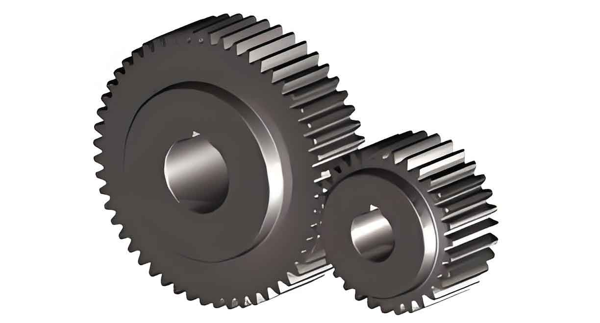
The reliable transmission of mechanical power in modern machinery is fundamentally dependent on the performance of gear systems. Among various gear types, spur gears are one of the most common and simplest forms, characterized by their straight, parallel teeth. Their widespread use in automotive transmissions, industrial gearboxes, and countless other applications is a testament to their design efficiency. However, under high-speed and heavy-load operating conditions, the meshing teeth of spur gears are subjected to extreme contact pressures and sliding/rolling motions. This inevitably leads to friction and wear on the tooth flanks, which can severely impact gear service life, load-carrying capacity, and overall transmission efficiency. Therefore, analyzing and enhancing the tribological performance of gear contact interfaces is a primary task for achieving near-zero wear in these fundamental transmission components.
Lubrication is the primary defense against friction and wear. Conventional lubricants, composed of base oils and additive packages, are designed to separate contacting surfaces with a protective film. The performance of these lubricants is highly dependent on the type and composition of their additives. In recent years, nano-additives have shown exceptional promise in enhancing tribological properties. Silicon nitride (Si₃N₄), a advanced ceramic material known for its high hardness, thermal stability, and excellent wear resistance, has emerged as a particularly effective solid lubricant additive. When dispersed in oil, silicon nitride nanoparticles can significantly improve anti-wear and friction-reduction performance through mechanisms such as mending effects, polishing, and the formation of protective tribofilms.
While previous research has explored the friction and wear performance of silicon nitride additives from a materials science perspective, a comprehensive study linking its effects to the specific lubrication regime governing spur gear operation—elastohydrodynamic lubrication (EHL)—is less common. EHL is the prevailing regime in heavily loaded, non-conformal contacts like gear teeth and rolling element bearings, where high pressure significantly increases lubricant viscosity and elastically deforms the contacting surfaces. This study aims to bridge this gap. I will investigate the influence of silicon nitride nanoparticles as a lubricant additive on the EHL performance of a spur gear pair. A mathematical model for EHL incorporating the modified properties of the Si₃N₄-enhanced oil will be established. This model will be solved computationally, and the results will be compared against a baseline model using conventional lubricant to quantify the benefits in terms of film thickness augmentation and friction reduction.
Theoretical Foundation and Mathematical Modeling
1. Geometric Model of Spur Gear Contact
The contact between meshing teeth of spur gears can be accurately modeled as a line contact problem. To simplify the analysis while retaining physical fidelity, the complex gear tooth geometry is等效d using the classic method of equivalent cylinders. The contact between two gear teeth is represented by the contact between an equivalent elastic cylinder of radius \(R\) and a rigid plane.
Consider two meshing spur gears with base circle radii \(R_a\) and \(R_b\), rotating with angular velocities \(\omega_a\) and \(\omega_b\), respectively. The pressure angle is \(\alpha\). The surface velocities at the contact point are \(U_a = \omega_a R_a\) and \(U_b = \omega_b R_b\). The entrainment velocity \(U\), which drives lubricant into the contact, is given by:
$$ U = \frac{U_a + U_b}{2} $$
The radius of the equivalent cylinder, \(R\), is derived from the relative curvature of the two contacting tooth profiles:
$$ R = \frac{R_a R_b}{R_a + R_b} $$
For a spur gear pair, the radii of curvature at a distance \(S\) from the pitch point are:
$$ R_a = R_{a_b} \tan \alpha + S $$
$$ R_b = R_{b_b} \tan \alpha – S $$
where \(R_{a_b}\) and \(R_{b_b}\) are the base circle radii. This equivalent model forms the geometric basis for all subsequent EHL analysis.
2. Mathematical Model for Lubricant with Silicon Nitride Additive
The incorporation of silicon nitride nanoparticles alters the fundamental rheological properties of the base oil. To model the lubricant mixture, we must define its effective viscosity and density. For a suspension of solid particles in a liquid, modified forms of classical mixture rules are applied. The effective dynamic viscosity \(\eta_0\) of the nano-lubricant at a reference temperature can be described by a model accounting for particle concentration and interaction:
$$ \eta_0 = \phi^n \eta_1 + (1-\phi)^n \eta_2 + 4\phi(1-\phi)\eta_2 e^{a – a\phi + b} $$
where:
\(\eta_1\) is the viscosity of the silicon nitride additive phase (often treated as an effective high-viscosity component).
\(\eta_2\) is the viscosity of the base oil.
\(\phi\) is the volume fraction of silicon nitride in the lubricant.
\(a\), \(b\), and \(n\) are empirical constants determined from rheological measurements of the specific nanofluid.
The effective density \(\rho_0\) of the mixture is calculated using a simple volumetric rule of mixtures:
$$ \rho_0 = \phi \rho_1 + (1-\phi) \rho_2 $$
where \(\rho_1\) and \(\rho_2\) are the densities of silicon nitride and the base oil, respectively. These modified properties (\(\eta_0\), \(\rho_0\)) are used as the inlet/p ambient condition values in the EHL equations.
3. Elastohydrodynamic Lubrication (EHL) Model
The EHL model consists of a set of coupled equations that must be solved simultaneously: the Reynolds equation governing pressure generation, the film thickness equation including elastic deformation, the force balance equation, and a constitutive equation for the fluid.
3.1. Generalized Reynolds Equation for Non-Newtonian Fluid
Under the high shear rates present in EHL contacts, lubricants often exhibit non-Newtonian behavior. The Ree-Eyring fluid model is a widely used constitutive law that captures the shear-thinning response. For a transient line contact, the generalized Reynolds equation for a Ree-Eyring fluid is:
$$ \frac{\partial}{\partial x} \left( \frac{\rho_e^* h^3}{\eta_e^*} \frac{\partial p}{\partial x} \right) = 12U \frac{\partial (\rho_e^* h)}{\partial x} + 12 \frac{\partial (\rho_e^* h)}{\partial t} $$
where \(p\) is the hydrodynamic pressure, \(h\) is the film thickness, and \(U\) is the entrainment speed. The averaged quantities \(\rho_e^*\) and \(\eta_e^*\) are integrals across the film thickness, defined as:
$$ \rho_e^* = \frac{1}{h} \int_0^h \rho \, dz $$
$$ \frac{1}{\eta_e^*} = \frac{1}{h} \int_0^h \frac{1}{\eta} \frac{z}{\eta_e’} \, dz $$
$$ \eta_e’ = \int_0^z \frac{z}{\eta} \, dz $$
The boundary conditions for pressure are:
$$ p(x_{in}, t) = 0 $$
$$ p(x_{out}, t) = 0 $$
$$ p(x, t) \geq 0 \quad \text{for} \quad x_{in} < x < x_{out} $$
3.2. Film Thickness Equation
The film thickness \(h\) in the contact zone is the sum of the geometric gap (which for the equivalent cylinder-on-plane model is parabolic), the constant separation \(h_0\), and the elastic deformation of the surfaces caused by the pressure distribution:
$$ h(x, t) = h_0(t) + \frac{x^2}{2R} – \frac{2}{\pi E’} \int_{x_{in}}^{x_{out}} p(s, t) \ln|x – s| \, ds $$
Here, \(E’\) is the effective elastic modulus of the contacting materials, given by:
$$ \frac{1}{E’} = \frac{1}{2} \left( \frac{1 – \nu_a^2}{E_a} + \frac{1 – \nu_b^2}{E_b} \right) $$
where \(E_a\), \(E_b\), \(\nu_a\), and \(\nu_b\) are the Young’s moduli and Poisson’s ratios of the two gear materials. The constant \(h_0(t)\) is determined by the force balance equation.
3.3. Force Balance Equation
The integrated pressure over the contact domain must equal the applied external load per unit length \(W\):
$$ \int_{x_{in}}^{x_{out}} p(x, t) \, dx = W $$
For spur gears, the load \(W\) varies along the path of contact and is related to the transmitted torque and tooth geometry.
3.4. Friction and Coefficient of Friction
The shear stress \(\tau\) within a Ree-Eyring fluid is related to the shear rate \(\dot{\gamma}\) by:
$$ \dot{\gamma} = \frac{\tau_0}{\eta} \sinh\left(\frac{\tau}{\tau_0}\right) $$
where \(\tau_0\) is the characteristic shear stress of the fluid. The friction force \(F_f\) is obtained by integrating the shear stress on the surfaces over the contact area. For computational purposes in line contact, the shear stress components (\(\tau_x\), related to rolling/sliding) are calculated from the velocity gradients. The total friction force per unit width is:
$$ F_f = \int_{\Omega} \tau_x \, d\Omega + \int_{\Omega} \frac{\partial p}{\partial x} \frac{h}{2} \, d\Omega $$
The coefficient of friction \(\mu\) is then:
$$ \mu = \frac{F_f}{W} $$
3.5. Dimensionless Analysis and Key Parameters
To generalize the solution and improve numerical stability, the governing equations are non-dimensionalized. Key dimensionless groups that govern EHL performance include the Hamrock-Dowson parameters for central \(H_c\) and minimum \(H_{min}\) film thickness in fully flooded, isothermal conditions:
$$ H_{min} = 2.65 \frac{U^{0.7} G^{0.54}}{W^{0.13}} $$
$$ H_{c} = 3.06 \frac{U^{0.69} G^{0.56}}{W^{0.10}} $$
where:
\(H = h/R\), \(U = \eta_0 U / (E’ R)\), \(G = \alpha E’\), and \(W = w / (E’ R)\).
Here, \(\alpha\) is the pressure-viscosity coefficient. These formulas, while approximate, highlight the strong dependence of film thickness on speed \(U\) and material parameter \(G\), and its weaker, negative dependence on load \(W\).
Simulation Methodology and Material Parameters
To analyze the effect of silicon nitride additives, I developed a numerical simulation framework in MATLAB. The solution process involves discretizing the dimensionless forms of the coupled EHL equations. The pressure field is solved using the multigrid method for efficiency, while the elastic deformation integral is calculated using the multigrid integration technique. The non-Newtonian Ree-Eyring behavior is iteratively accounted for in the viscosity profile across the film.
The simulation compares two cases: a baseline lubricant (Case A) and the same lubricant enhanced with a volume fraction \(\phi\) of silicon nitride nanoparticles (Case B). The key parameters for the spur gear pair and lubricants are summarized in the table below.
| Parameter | Symbol | Value (Case A / Base) | Value (Case B / Si₃N₄) | Unit |
|---|---|---|---|---|
| Number of Teeth (Driver) | \(z_1\) | 54 | – | |
| Number of Teeth (Driven) | \(z_2\) | 27 | – | |
| Module | \(m\) | 5 | mm | |
| Face Width | \(b\) | 30 | mm | |
| Pressure Angle | \(\alpha\) | 20 | ° | |
| Young’s Modulus (Gear Steel) | \(E_a, E_b\) | 210 | GPa | |
| Poisson’s Ratio | \(\nu_a, \nu_b\) | 0.3 | – | |
| Input Speed | \(n\) | 1400 | rpm | |
| Input Torque | \(T\) | 600 | Nm | |
| Base Oil Viscosity (@40°C) | \(\eta_2\) | 0.078 | Pa·s | |
| Base Oil Density | \(\rho_2\) | 876 | kg/m³ | |
| Si₃N₄ Density | \(\rho_1\) | 3180 | kg/m³ | |
| Pressure-Viscosity Coefficient | \(\alpha\) | 2.2×10⁻⁸ | m²/N | |
| Ree-Eyring Characteristic Stress | \(\tau_0\) | 7 | MPa | |
| Si₃N₄ Volume Fraction | \(\phi\) | 0 | 0.02 | – |
| Effective Mixture Viscosity | \(\eta_0\) | 0.078 | 0.095 | Pa·s |
| Effective Mixture Density | \(\rho_0\) | 876 | 922.1 | kg/m³ |
Results and Discussion
1. Effect on Film Thickness and Pressure Profile
The primary result of the simulation is the comparison of the pressure and film thickness profiles along the centerline of the contact for both lubricant cases. The most striking observation is the increase in film thickness when using the silicon nitride additive. The typical EHL pressure spike near the contact outlet remains present in both cases, with the maximum Hertzian pressure being nearly identical because it is primarily governed by the applied load and material properties. However, the film profile in the central and inlet regions is notably thicker for Case B.
This film thickening can be attributed to two main factors stemming from the additive’s presence. First, the effective inlet viscosity \(\eta_0\) of the nano-lubricant is higher than that of the base oil, as calculated by the mixture model. Since film thickness in the inlet zone scales positively with viscosity (e.g., \(H \propto U^{0.7} \eta^{0.7}\)), a higher inlet viscosity directly promotes a thicker film entering the high-pressure contact. Second, under severe conditions, the nanoparticles may mechanically resist the “thinning” of the film in the central contact region. They are postulated to act as miniature spacers or rolling elements, providing an additional mechanism to separate the surfaces and maintain film integrity under heavy load, thereby mitigating the “pressure-thinning” effect to some degree.
| Performance Indicator | Case A: Base Oil | Case B: Si₃N₄ Nano-lubricant | Relative Change |
|---|---|---|---|
| Minimum Film Thickness, \(h_{min}\) (nm) | 152 | 185 | +21.7% |
| Central Film Thickness, \(h_c\) (nm) | 320 | 365 | +14.1% |
| Maximum Hertzian Pressure, \(p_{max}\) (GPa) | 1.12 | 1.11 | ~ -0.9% |
| Coefficient of Friction, \(\mu\) (Averaged) | 0.038 | 0.031 | -18.4% |
| Lambda Ratio (\(\lambda = h_{min}/\sigma)\)* | 2.53 | 3.08 | +21.7% |
| *Assuming a composite surface roughness \(\sigma = 0.06 \mu m\). A \(\lambda > 3\) indicates a more robust full-film lubrication. | |||
2. Effect on Friction Coefficient
The reduction in the coefficient of friction is another significant finding. The friction coefficient over the path of contact for the spur gears follows a characteristic “friction hill” shape for both lubricants. However, the curve for the silicon nitride-enhanced lubricant lies consistently below that of the base oil. At the pitch point, where pure rolling occurs, the friction coefficient is theoretically zero for both, which is reflected in the simulations. In the regions of high sliding (near the start and end of contact), the friction reduction is most pronounced.
This friction reduction mechanism is multi-faceted. The increased film thickness itself reduces the share of boundary or mixed lubrication interactions. More importantly, the silicon nitride nanoparticles are known to form a protective, low-shear-strength tribochemical film on the metal surfaces during sliding contact. This film shears more easily than direct metal-to-metal or metal-to-base-oil interactions. Furthermore, the spherical nanoparticles may induce a “rolling-sliding” effect at the asperity level, converting some sliding friction into rolling friction, which is inherently lower. The combination of a thicker hydrodynamic film and these boundary-layer modifications leads to the observed overall decrease in the friction coefficient for the spur gear system.
3. Implications for Spur Gear Performance and Durability
The improvements quantified in Table 2 have direct and positive implications for the operational performance and lifespan of spur gears.
- Wear Reduction: The increase in both minimum film thickness and the lambda ratio (\(\lambda\)) significantly lowers the probability of asperity contact. This directly translates to reduced adhesive, abrasive, and fatigue (micropitting) wear on the tooth flanks.
- Efficiency Gain: A lower friction coefficient directly reduces power losses in the gear mesh, improving the overall transmission efficiency. This is crucial for energy-intensive applications.
- Scuffing Resistance: The enhanced film-forming capability provides a greater safety margin against lubricant film collapse under shock loads or temperature spikes, thereby increasing resistance to scuffing (severe adhesive wear).
- Thermal Management: Lower friction generates less frictional heat at the contact, potentially leading to lower bulk operating temperatures for the gears and the lubricant, which helps maintain lubricant viscosity and performance.
Conclusion
In this study, I have developed and analyzed an elastohydrodynamic lubrication model for spur gears operating with a lubricant enhanced by silicon nitride nanoparticles. The key conclusions are as follows:
- Silicon nitride nanoparticles act as an effective performance modifier for gear oils. By increasing the effective viscosity in the inlet zone and potentially providing micro-scale mechanical separation, they significantly augment the elastohydrodynamic film thickness between the meshing teeth of spur gears. In the simulated heavy-load condition, the minimum film thickness increased by over 20%.
- The incorporation of silicon nitride additives leads to a substantial reduction in the coefficient of friction for the spur gear contact. This is attributed to the synergistic effect of a thicker separating film and the formation of low-shear-strength boundary films by the nanoparticles, which ease interfacial slip.
- The combined effect of increased film thickness and reduced friction directly translates to tangible benefits for spur gear systems: enhanced wear protection, improved transmission efficiency, greater operational reliability, and potentially extended service life.
This investigation provides a theoretical and computational foundation for the application of silicon nitride nano-additives in gear lubrication. Future work should focus on experimental validation using gear test rigs, exploring the effects of different nanoparticle sizes and concentrations, and modeling more complex thermal and non-Newtonian interactions under a wider range of operating conditions for spur gears.