
In the automotive industry, the demand for improved NVH (Noise, Vibration, and Harshness) performance has become increasingly critical as consumers prioritize driving comfort and quality. The rear axle final drive assembly, which relies heavily on spiral bevel gears, is a significant contributor to overall vehicle noise. As such, reducing the noise generated by these gears is a paramount concern for manufacturers. A key factor influencing the啮合 noise of spiral bevel gear pairs is the Transmission Error (TE) value. TE serves as the primary excitation source for gear vibration, and the dynamic performance of gears is largely determined by this parameter. In this article, I will delve into the concept of TE, explore the major factors affecting it in spiral bevel gears, and discuss practical control methods utilizing modern design software and manufacturing technologies.
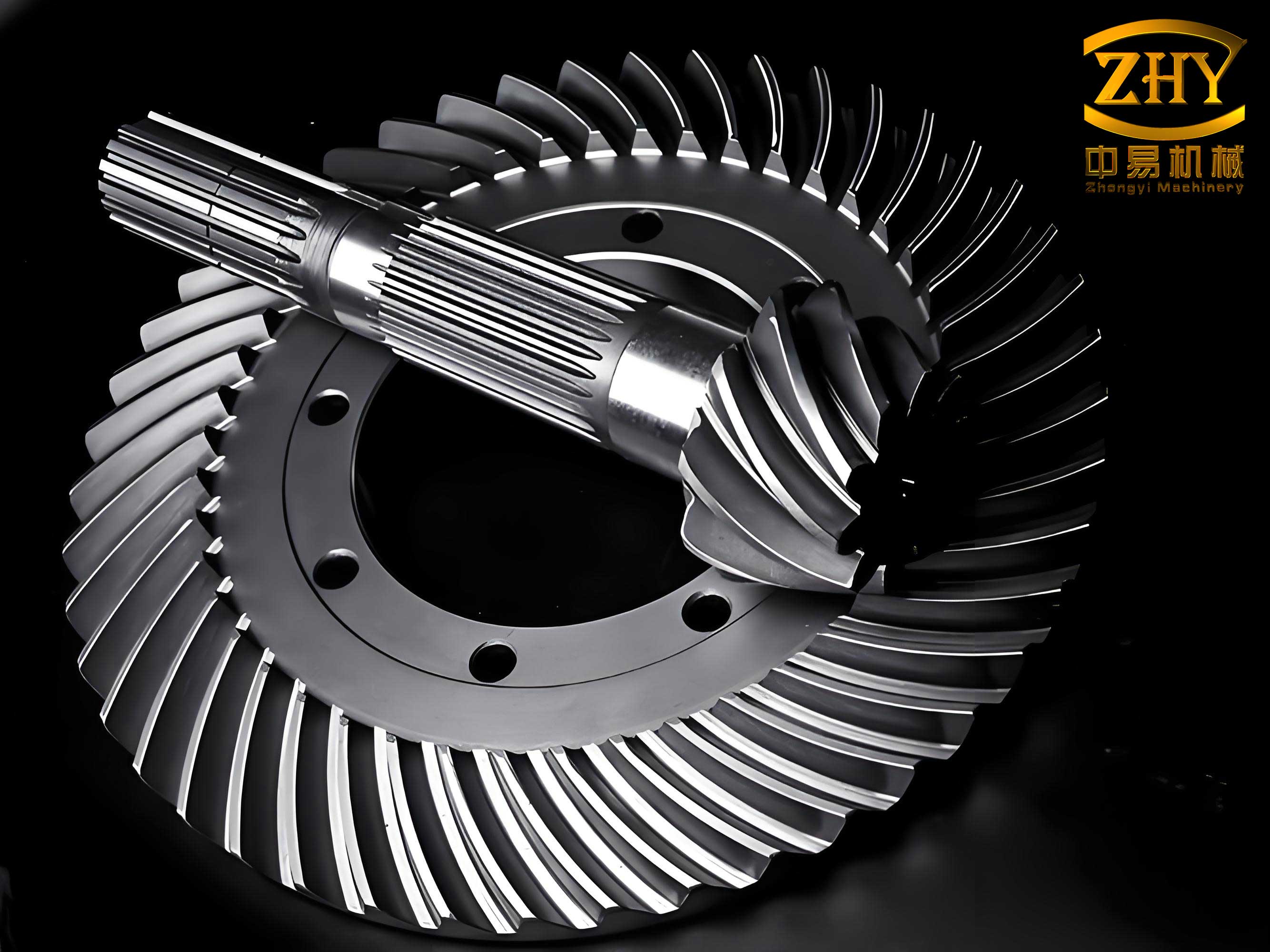
The Transmission Error (TE) in a pair of spiral bevel gears is defined as the deviation in the angular position of the driven gear from its ideal location when the driving gear rotates at a constant speed. Under perfect conditions—assuming no manufacturing or assembly errors, ideal tooth profiles (such as circular arc or extended epicycloid), rigid materials, and no load—the driven gear would rotate uniformly. However, in reality, imperfections exist. To achieve desirable tooth contact patterns, design and machining processes often involve modifications to the tooth surfaces. Additionally, elastic deformation under load occurs. These factors cause the driven gear to rotate non-uniformly when the driving gear rotates uniformly. This non-uniformity, quantified as TE, is the fundamental “excitation” that leads to gear vibration and noise. Mathematically, for a given啮合 point along the line of action, TE can be expressed as the linear displacement error along this line, which correlates to an angular error on the driven gear. If we denote the ideal angular position of the driven gear as $\theta_{ideal}$ and the actual angular position as $\theta_{actual}$, the TE in angular terms can be represented as $\Delta \theta = \theta_{actual} – \theta_{ideal}$. Over the course of mesh, this error varies, and its fluctuation directly reflects the non-uniform rotation. The peak-to-peak variation of TE is often used as a key metric. In practice, TE is typically measured in micro-radians (μrad). For spiral bevel gears, controlling TE is essential for achieving quiet operation.
Traditionally, the quality of spiral bevel gear pairs has been assessed primarily through contact pattern inspection under light load, where a marking compound is applied to the teeth. While contact pattern provides valuable information about tooth bearing and strength, it offers limited insight into dynamic performance. With advancements in measurement technology, high-precision TE measurement devices, such as those incorporating encoders to monitor angular positions of both gears under low-torque conditions, have become instrumental. These devices allow for a comprehensive evaluation of TE throughout the mesh cycle. The relationship between TE and dynamic excitation can be understood through the equation for vibrational response. The dynamic force $F_d$ excited by TE can be modeled as $F_d = k \cdot TE$, where $k$ represents the effective mesh stiffness. Minimizing TE directly reduces this excitation force, thereby lowering noise and vibration levels.
Several factors influence the TE value in spiral bevel gears. These can be categorized into design parameters, manufacturing processes, and post-processing techniques. Below, I will discuss these in detail, employing formulas and tables to summarize key points.
Design Parameters Affecting TE
The initial design of spiral bevel gears plays a crucial role in determining the inherent TE. Software tools like Oerlikon KIMOS5 are used to optimize designs for low TE. Two primary tooth types are prevalent: Gleason-type (coniflex or tapered tooth) and Oerlikon-type (constant depth tooth). Each has different implications for TE control.
1. Tooth Type and Process: For Gleason-type spiral bevel gears (tapered tooth), grinding is often employed as a finishing process. This allows for precise control of tooth geometry, enabling TE values to be maintained at low levels. During design, the target TE for such gears is typically set below 70 μrad. For instance, in a bus rear axle gear set (module 10.1, ring gear outer diameter 435 mm), the designed TE values might be 41.7 μrad for drive side and 34.2 μrad for coast side. After cutting, heat treatment, and grinding on machines like the Oerlikon C50 and G60, the measured TE values can be as low as 39.7 μrad and 39.6 μrad, respectively. This demonstrates the effectiveness of modern grinding processes in achieving design targets.
For Oerlikon-type spiral bevel gears (constant depth tooth), heat treatment distortion is more significant, and lapping is commonly used for final correction. During design, TE targets are slightly relaxed to account for distortion—typically below 85 μrad for heavy-duty gears (ring gear OD > 400 mm) and below 70 μrad for light-duty gears. However, post-lapping, TE can be reduced substantially. For example, a light-duty gear set (module 5.6, ring gear OD 229 mm) might have designed TE values of 56.2 μrad (drive) and 46.5 μrad (coast). After cutting on an Oerlikon C27 and heat treatment, distortion may increase TE to 82.28 μrad and 115.27 μrad. After lapping on an Oerlikon L60 machine, TE can be dramatically improved to 13.1 μrad and 19.43 μrad. This highlights the critical role of lapping in compensating for heat treatment effects on spiral bevel gears.
| Tooth Type | Primary Finishing Process | Typical Designed TE Target (μrad) | Post-Process Typical Achieved TE (μrad) | Key Challenge |
|---|---|---|---|---|
| Gleason (Tapered Tooth) | Grinding | < 70 | ~40-50 | Precision grinding setup |
| Oerlikon (Constant Depth Tooth) | Lapping | < 70 (Light) / < 85 (Heavy) | ~15-30 after lapping | Heat treatment distortion compensation |
2. Spiral Angle: The spiral angle ($\beta$) significantly affects the contact pattern length and position. It also influences TE. For spiral bevel gears using grinding, the spiral angle is optimized to position the contact pattern appropriately while keeping TE below the target. For lapped spiral bevel gears, heat treatment often causes spiral angle distortion. Therefore, the design must incorporate a compensation factor, adjusting the nominal spiral angle so that after distortion, the effective angle aligns with the desired contact pattern. This compensation may result in higher designed TE values, but lapping subsequently corrects it. The relationship between spiral angle error ($\Delta \beta$) and TE change ($\Delta TE$) can be approximated as $\Delta TE \propto \Delta \beta \cdot L$, where $L$ is the face width. Thus, precise control of spiral angle during design and manufacturing is vital for spiral bevel gears.
3. Inner Diagonal (Pressure Angle Variation): The inner diagonal, or bias, refers to the asymmetry in pressure angles across the tooth face. A proper inner diagonal increases the overlap ratio (contact ratio) of the spiral bevel gear pair, smoothing the transition of load between teeth and reducing TE fluctuations. The overlap ratio $\epsilon_{\gamma}$ for spiral bevel gears can be expressed as $\epsilon_{\gamma} = \frac{\text{Length of path of contact}}{\text{Base pitch}}$. A higher $\epsilon_{\gamma}$ generally leads to lower TE amplitude. Modern design software like KIMOS5 incorporates dry-cutting techniques that inherently introduce an optimal inner diagonal. Reducing the inner diagonal excessively can cause a sharp increase in TE. Therefore, for lapped spiral bevel gears, it is important not to eliminate the inner diagonal completely during lapping for visual appeal; instead, a light lapping should be performed to preserve the designed bias and maintain low TE.
The effect of inner diagonal on TE can be summarized by the following empirical relation for spiral bevel gears: $$ TE_{peak} \approx \frac{K_1}{\epsilon_{\gamma}} + K_2 \cdot \Delta \alpha $$ where $\Delta \alpha$ represents the pressure angle asymmetry (inner diagonal), and $K_1$, $K_2$ are constants dependent on gear geometry. An optimal $\Delta \alpha$ minimizes $TE_{peak}$.
Manufacturing and Process Control
Beyond design, manufacturing accuracy is paramount for controlling TE in spiral bevel gears. Key manufacturing factors include tooth spacing errors, profile deviations, surface roughness, and heat treatment distortion.
1. Tooth Spacing and Profile Accuracy: Cumulative pitch error ($F_p$) and individual pitch error ($f_{pt}$) directly contribute to TE variations. For a gear with $N$ teeth, the TE component due to pitch errors can be modeled as: $$ TE_{pitch} = \frac{2 \pi}{N} \cdot \frac{\sum_{i=1}^{N} |f_{pt_i}|}{2 \pi R_{base}} $$ where $R_{base}$ is the base radius. High-precision cutting machines like the Oerlikon C series ensure minimal pitch errors.
2. Heat Treatment Distortion: This is a major challenge, especially for constant depth spiral bevel gears. Distortion alters tooth geometry, affecting both contact pattern and TE. The distortion can be characterized by changes in spiral angle, pressure angle, and tooth thickness. Compensations are applied during cutting—for example, pre-correcting the tooth surfaces so that after distortion, they approximate the desired shape. The lapping process then fine-tunes the surfaces to achieve low TE. The distortion compensation requires extensive empirical data and simulation.
3. Finishing Processes: Grinding vs. Lapping: As mentioned, grinding is used for tapered tooth spiral bevel gears, offering high precision and repeatability. The grinding process removes material to achieve the final geometry, directly controlling TE. Lapping, used for constant depth spiral bevel gears, involves running the gear pair with an abrasive compound to correct minor errors. It improves surface finish and adjusts the contact pattern, thereby reducing TE. The material removal during lapping is minimal, typically a few micrometers. The effectiveness of lapping can be expressed in terms of TE reduction per lapping cycle: $$ \Delta TE_{lapping} = \eta \cdot (TE_{initial} – TE_{target}) $$ where $\eta$ is the lapping efficiency factor (typically 0.8-0.95 per cycle).
| Manufacturing Factor | Effect on TE | Control Method | Typical Tolerance |
|---|---|---|---|
| Tooth Spacing Error | Increases TE fluctuation at tooth mesh frequency | High-precision cutting/grinding | $f_{pt} < 5 \mu m$ |
| Profile Deviation | Causes localized TE spikes | Optimized tool design and CNC path | Profile error < 10 μm |
| Spiral Angle Error | Shifts contact pattern, increases TE | Distortion compensation in design | $\Delta \beta < 0.1^\circ$ |
| Surface Roughness | Affects friction and minor TE harmonics | Grinding/lapping to Ra < 0.4 μm | Ra < 0.4 μm |
Software-Based Design for TE Optimization
Modern gear design software, such as Oerlikon KIMOS5, enables comprehensive TE analysis and optimization during the design phase. These tools use numerical simulations to predict TE based on design parameters, manufacturing corrections, and load conditions. The software can perform sensitivity analysis to identify which parameters most influence TE for spiral bevel gears.
The basic equation for TE in simulation often derives from the tooth contact analysis (TCA). The transmission error function $TE(\phi)$ as a function of pinion rotation angle $\phi$ is computed by solving the啮合 equations considering tooth flexibility. A simplified representation is: $$ TE(\phi) = \frac{\theta_{gear}(\phi) – (N_p/N_g)\phi}{N_g} $$ where $N_p$ and $N_g$ are the numbers of teeth on pinion and gear, and $\theta_{gear}(\phi)$ is the actual gear rotation angle from TCA. The software aims to minimize the peak-to-peak value of $TE(\phi)$.
Key design variables adjusted in software for spiral bevel gears include:
- Machine tool settings (cutter radius, blade angle, etc.)
- Ease-off topography (modified tooth surfaces)
- Pressure angle and spiral angle distributions
- Inner diagonal amount
By iterating these variables, the software can achieve a design with low TE while maintaining a satisfactory contact pattern. For instance, KIMOS5 incorporates algorithms that balance TE and contact stress. The optimization goal can be formulated as: $$ \text{Minimize } \max(|TE(\phi)|) \text{ subject to } \sigma_{contact} < \sigma_{allowable} $$
Moreover, the software can generate manufacturing data for CNC machines, ensuring that the designed geometry is accurately produced. This closed-loop design-manufacturing process is essential for consistent TE control in spiral bevel gears.
Production Applications and Case Studies
With the rise of electric commercial vehicles, noise from the rear axle has become more pronounced due to the absence of engine masking noise. Therefore, spiral bevel gears with low TE are in high demand for electric vehicle axles. Traditional rear axle gears for large vehicles (ring gear OD ~460 mm, module >10) typically have noise levels around 78 dB at 800 rpm. However, electric vehicles require quieter operation, often targeting 68-74 dB at 1000 rpm.
By focusing on TE control, manufacturers can meet these stringent requirements. For example, using TE measurement devices like the Oerlikon T60, the TE values of gear sets are monitored and optimized. Through design adjustments and precision manufacturing, TE values can be reduced to levels that yield the desired noise performance. Success stories include supplying spiral bevel gears to axle manufacturers like Fang Sheng and Ankai, where TE-controlled gears replaced imported ones, reducing cost while improving NVH.
The correlation between TE and noise level ($L_{noise}$) can be empirically expressed for spiral bevel gears as: $$ L_{noise} \propto 20 \log_{10}(TE_{peak}) + C $$ where $C$ is a constant depending on installation and load conditions. Thus, reducing TE from 80 μrad to 40 μrad can yield approximately 6 dB noise reduction, a significant improvement.
In one case study, for a spiral bevel gear set used in an electric bus axle, the following process was implemented:
- Design using KIMOS5 targeting TE < 50 μrad.
- Precision cutting on Oerlikon C50 with closed-loop correction.
- Controlled heat treatment with distortion prediction.
- Finishing by grinding (for tapered tooth) or lapping (for constant depth).
- TE measurement on T60 and noise testing on a gear roll tester.
The final product achieved TE values around 30 μrad and noise levels of 70 dB at 1000 rpm, satisfying the electric vehicle requirements.
Advanced Considerations and Future Trends
Beyond traditional factors, advanced topics in spiral bevel gear TE control include the effects of lubrication, micro-geometry corrections, and system dynamics. Lubricant film thickness can slightly alter effective tooth stiffness, influencing TE. Micro-geometry corrections such as tip and root relief are applied to avoid edge contact and reduce TE shocks. These corrections are often described by parabolic functions. For example, the relief amount $\delta(s)$ along the profile direction $s$ can be: $$ \delta(s) = C_{rel} \cdot (s – s_0)^2 $$ where $C_{rel}$ is the relief coefficient and $s_0$ is the start point. Optimizing these corrections further minimizes TE.
System dynamics also play a role. The TE excitation interacts with the resonant frequencies of the gearbox structure. Therefore, a comprehensive approach considers the full dynamic model: $$ I_p \ddot{\theta}_p + k_m (R_p \theta_p – R_g \theta_g – TE(t)) = T_p $$ $$ I_g \ddot{\theta}_g – k_m (R_p \theta_p – R_g \theta_g – TE(t)) = -T_g $$ where $I_p$, $I_g$ are inertias, $k_m$ is mesh stiffness, $R_p$, $R_g$ are base radii, and $T_p$, $T_g$ are torques. Minimizing TE reduces the forcing term in these equations.
Future trends in spiral bevel gear manufacturing include the use of artificial intelligence for predictive distortion compensation, additive manufacturing for prototype gears, and even more integrated software-hardware systems for real-time TE monitoring during production.
Conclusion
In summary, Transmission Error (TE) is a critical parameter governing the noise and vibration performance of spiral bevel gears. Controlling TE involves a holistic approach encompassing design optimization, precision manufacturing, and appropriate finishing processes. Key factors such as tooth type, spiral angle, inner diagonal, pitch accuracy, and heat treatment distortion must be meticulously managed. Modern software like Oerlikon KIMOS5, coupled with advanced machines for cutting, grinding, and lapping, enables effective TE control. As the automotive industry shifts towards electric vehicles, the demand for low-TE spiral bevel gears will only increase. By focusing on TE reduction throughout the production cycle, manufacturers can achieve superior NVH characteristics, meeting the evolving standards for quiet and reliable drivetrains. The continuous improvement in spiral bevel gear technology ensures that these essential components will keep pace with the industry’s demands for performance and comfort.