The dual frequency induction quenching process of bevel gear can be divided into induction heating process and quenching cooling process. This chapter first simulates the microstructure of the quenching and cooling process of bevel gear, and explains the depth of the hardened layer from the microstructure distribution. Then, the double frequency induction heating experimental platform of bevel gear is built by using the medium and high frequency power supply and other equipment in the laboratory, and the double frequency induction heating experiment is carried out, and the temperature measurement data is compared with the simulation data.
Because the induction heating process and quenching process of bevel gear adopt a unified grid model, it is not difficult to import the temperature field after dual frequency induction heating from ANSYS software into DEFORM software.
Different from the general heat treatment method, after induction heating, only the surface structure of bevel gear is austenitized, and its internal structure is not austenitized. Therefore, the initial structure field of bevel gear quenching and cooling is not uniform austenitic structure, so it is necessary to define the initial structure field of quenching and cooling. There are generally two methods to define the initial structure field. One is to ignore the influence of heating speed and other parameters on the austenite process of bevel gear structure, that is, it is assumed that the structure of the unit higher than the austenitizing temperature of 760 º C is austenitic structure. This method is called simple temperature method. The other is to consider the austenitizing process in the process of induction heating. To define the initial microstructure field, it is necessary to establish the austenitizing dynamic model. This method is called the austenitizing dynamic model method. The second method has high numerical simulation accuracy, but it needs to be programmed by itself. In this chapter, the first method, that is, the simple temperature method, is used to define the initial tissue field, and then the quenching simulation is carried out.
1. heat source introduction and initial organization definition
The initial temperature field and microstructure field need to be defined to simulate the quenching and cooling process of bevel gear after induction heating. When carrying out quenching cooling analysis in deform, it is necessary to import the temperature field model obtained in ANSYS into deform as the heat source of quenching cooling analysis. When ANSYS software simulates and analyzes the dual frequency induction heating process of bevel gear, only the temperature field model is obtained, but the tissue field model can not be obtained. Therefore, when simulating the quenching and cooling process of bevel gear, the initial tissue field can not be obtained directly.
In ANSYS software, it is realized by directly using APDL language to write command flow. The initial temperature field of the quenching field can be extracted from the ANSYS DEM form software, so that the initial temperature field can be imported into the ANSYS form.
The initial structure field of quenching and cooling simulation in deform is defined by simple temperature method, that is, the unit structure is defined according to the temperature value of the unit after induction heating. If the unit temperature reaches the austenitizing temperature of 760 º C after induction heating, the structure is defined as austenitic structure, and all the unit structures that do not reach this temperature are defined as pearlite structure. In fact, during the heating process of the specimen, the organization of the unit is also related to the heating speed and holding time, which is not considered in this paper. The material library of DEFORM software is equipped with 45 steel material for microstructure field simulation, which contains three kinds of microstructure: austenite, pearlite and bainite. For a specific unit, deform defines its structure state in the form of percentage. If the unit is completely Austenitic, its percentage is 1.
2. Setting of boundary conditions
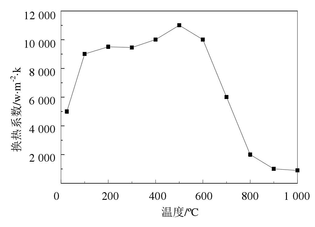
The bevel gear after induction heating is quenched by water cooling process. In the actual quenching process, the boundary conditions of bevel gear are complex, including convective heat transfer and radiation heat transfer, and the quenching process of bevel gear is not simple. Next, the water cooling numerical simulation of the bevel gear after dual frequency induction heating is carried out, and only the microstructure distribution of the quenched bevel gear is analyzed. For the heat exchange coefficient, the general comprehensive heat exchange coefficient is adopted, and the specific value of the heat exchange coefficient is shown in the figure.

