
After induction heating, the bevel gear will be quenched and cooled. Different microstructure distribution can be obtained by using different bevel gear temperature field models for quenching simulation. Next, the temperature field models of single and dual frequency induction heating are compared, and then the tissue field model is analyzed. The parameters of dual frequency induction heating are as follows: the frequency and density of high frequency current are 100kHz and 6 respectively × 107a / m2, the frequency and density of intermediate frequency current are 3kHz and 1.5 respectively × 108a / m2, the total induction heating time is 45s, the output time ratio of medium and high frequency current is 2:1, and the switching times is 30; The current frequency and density of single frequency induction heating are set as 3kHz and 1.5 respectively × 108A/m2; 52s for induction heating.
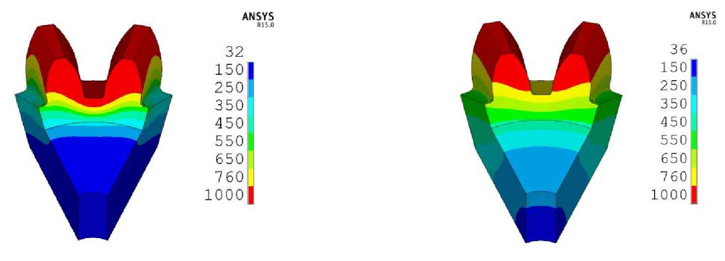
Figure 1 shows the bevel gear temperature field model obtained by single and dual frequency induction heating. It can be seen that the tooth root of the temperature field model obtained by single frequency induction heating does not reach the austenitizing temperature, while the tooth profile of the temperature field model obtained by dual frequency induction heating reaches the austenitizing temperature to a certain depth.
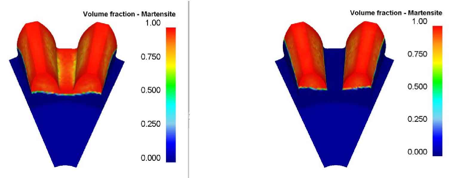
Comparing Fig. 2a) and Fig. 2b), it is obvious that the temperature field model with more uniform distribution along the tooth profile obtained after dual frequency induction heating can obtain the martensite structure distributed along the tooth profile after quenching and cooling.
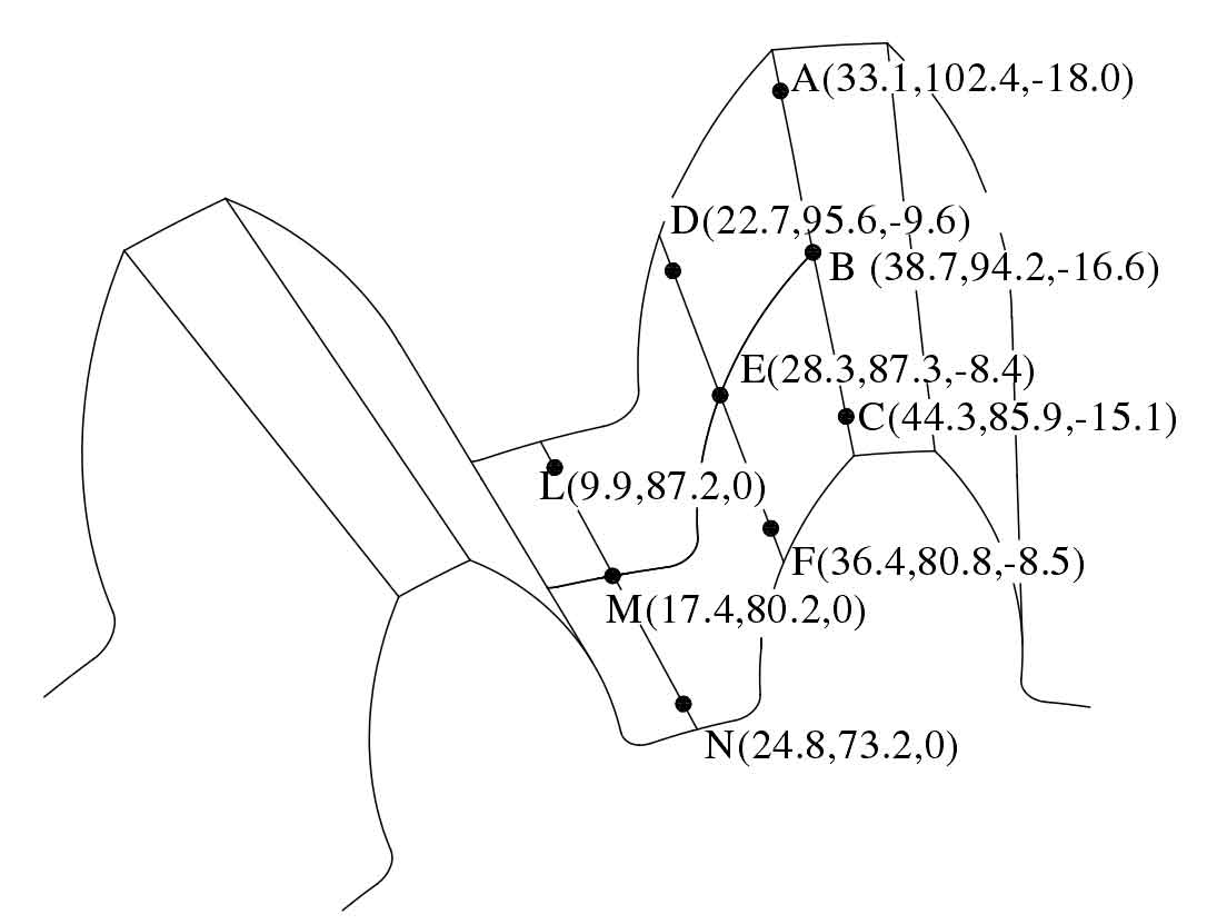
Select 9 points as shown in Figure 3: A, B, C, D, e, F, l, m and N, where a, B and C are located at the top of the tooth, D, e and F are located in the middle of the tooth surface, and l, m and N are located at the root of the tooth. Considering that there is a deep hardening layer at the end of the bevel gear due to the end effect during induction heating, select a, D, l, C, F and N as 5mm away from the end of the tooth. The martensite content at these 9 points and their depth of 2.5mm is extracted and made into a table, as shown in Table 1.
| A | B | C | D | E | F | L | M | N | ||
| Dual frequency quenching | surface | 99.1 | 98.7 | 99.5 | 97.6 | 93.7 | 98.2 | 97.6 | 99.1 | 99.4 |
| Dual frequency quenching | 2.5mm deep | 92.4 | 86.4 | 93.8 | 83.0 | 76.1 | 83.3 | 57.9 | 65.7 | 58.7 |
| Single frequency quenching | surface | 99.2 | 98.9 | 99.7 | 94.5 | 88.7 | 96.5 | 0 | 0 | 0 |
| Single frequency quenching | 2.5mm deep | 89.9 | 82.2 | 92.1 | 47.7 | 40.3 | 78.6 | 0 | 0 | 0 |
Comparing the martensite content data obtained by dual frequency induction quenching and single frequency induction quenching in Table 1, it can be seen that single frequency induction quenching does not harden the tooth root, while the martensite content of the surface layer and 2.5mm deep of the tooth root and tooth surface of the dual frequency induction quenched bevel gear exceeds 50%, Generally, the depth of induction hardening layer is defined as the thickness from the surface layer of the workpiece with 100% martensite content to 50% martensite area in the vertical depth direction.
Using 9 points in Fig. 3, the distribution of martensite structure after single and double frequency induction quenching is analyzed from the depth direction of bevel gear surface.
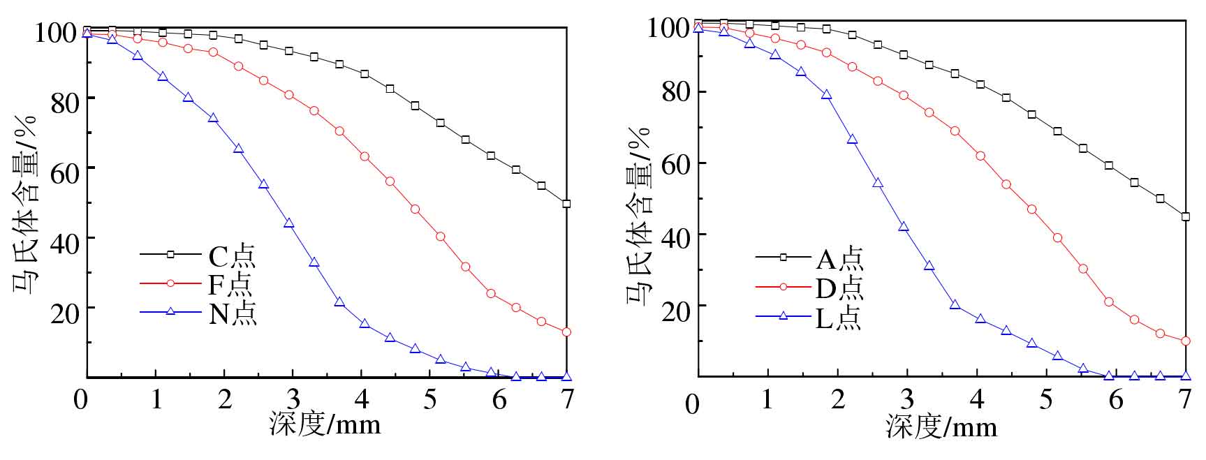
Comparing FIG. 4A) and b), it can be seen that the distribution law of martensite content is basically the same along the direction of tooth depth at the top, root and midpoint of bevel gear. It can be seen from table 2 that the hardening layer depth of the small end of the bevel gear is slightly higher than that of the big end.
| A | C | D | F | L | N | |
| Hardened layer depth | 6.7 | 6.9 | 4.5 | 4.2 | 2.6 | 2.8 |
The distribution of martensite content in the depth direction of the hardened layer is analyzed, as shown in Fig. 5 and table 3. Comparing the hardened layer depth of single and dual frequency induction quenching, it can be seen that the hardened layer depth of point B on the tooth top is the deepest, followed by point E on the tooth surface, and finally point m on the tooth root. In actual factory production, the requirements for the hardened layer depth of tooth surface and tooth root will also be different.
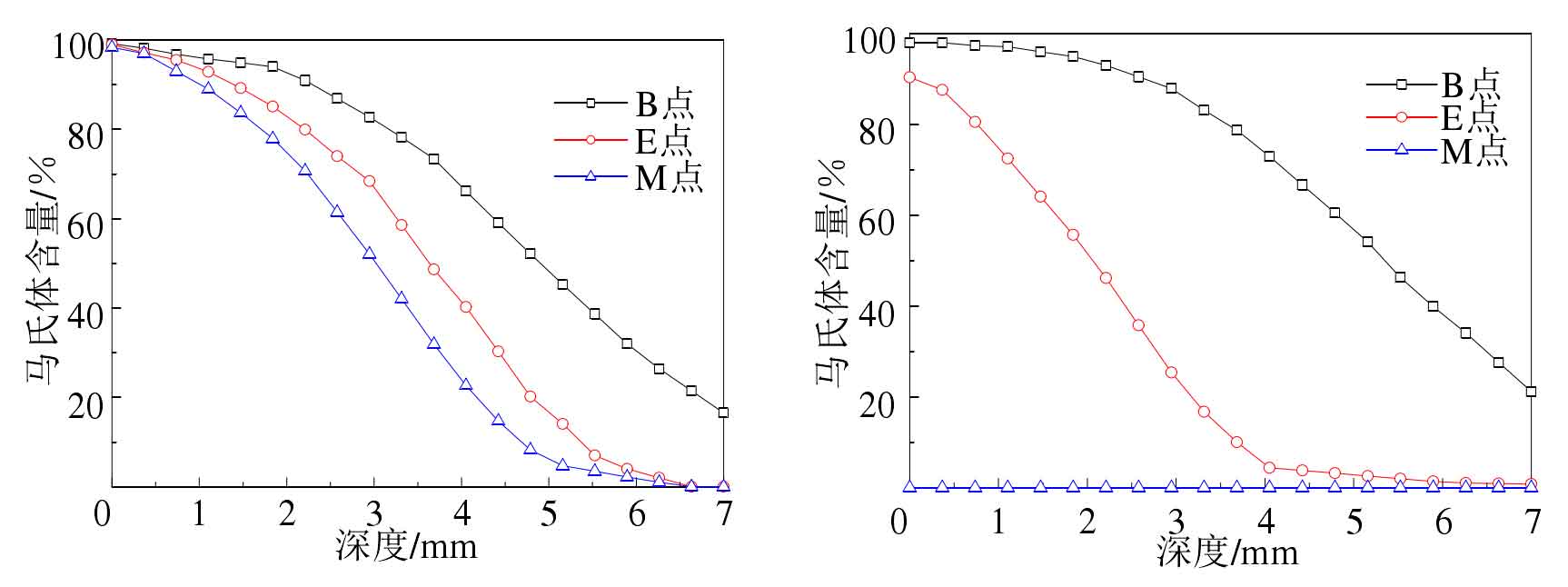
When the bevel gear is heated by dual frequency induction, because the volume of the tooth top area is relatively small and there are sharp corners, the induction heating efficiency is high, the austenitizing structure on the surface layer is deep, and the tooth root is close to the bevel gear matrix. During induction heating, the matrix almost does not directly participate in the induction heating process, so the temperature of the matrix is generally low, resulting in the low austenitizing depth of the tooth root. The deeper austenite structure will generally generate deeper martensite structure during quenching and cooling. The specific depth of martensite structure is not only related to the depth of austenite structure, but also related to quenching and cooling process.
| B | E | M | |
| Dual frequency induction quenching | 4.8 | 3.5 | 3.0 |
| Single frequency induction quenching | 5.2 | 1.8 | 0 |
It can be seen from table 3 that the hardened layer depth of the tooth top of single frequency induction quenching is 0.4mm higher than that of dual frequency induction quenching, which is due to the high induction heating efficiency of the tooth top during single frequency induction heating, but the hardened layer depth of the tooth root of single frequency induction quenching is 0mm. The induction hardening quality of bevel gear is better than that of single frequency induction hardening.