
In my extensive experience with precision manufacturing, I have encountered numerous challenges in gear shaping processes, particularly when dealing with advanced materials like titanium alloys. This article delves into a comprehensive study I conducted on gear shaping for thin-walled titanium alloy flanges, which are critical components in aerospace applications. The inherent properties of titanium alloys, combined with the geometric constraints of thin-walled structures, make the gear shaping operation exceptionally difficult. My goal was to develop a robust methodology that ensures high accuracy in internal spline machining, specifically achieving tight tolerances for runout before and after subsequent processes like shot peening.
The primary issue revolves around the gear shaping of internal splines on thin-walled titanium flanges. Titanium alloys, such as Ti-6Al-4V, exhibit several characteristics that adversely affect machining: low thermal conductivity, high chemical reactivity, and a tendency to work-harden. During gear shaping, these factors lead to rapid tool wear, high cutting temperatures, and significant cutting forces, often resulting in tool chipping and adhesion wear. Moreover, the thin-walled nature of the flange exacerbates deformation under cutting loads, compromising the dimensional accuracy of the internal spline. The precision requirements are stringent; the runout of the internal spline must be within 0.025 mm after gear shaping and within 0.03 mm after shot peening. Traditional gear shaping approaches for steel components are inadequate here, necessitating a holistic redesign of the tooling, fixturing, and cutting parameters specifically for titanium gear shaping.
My research focused on three core areas: first, selecting and optimizing the gear shaping tool to withstand the harsh conditions of titanium machining; second, redesigning the fixture to counteract deformation forces and enhance part rigidity during gear shaping; and third, meticulously optimizing the cutting parameters, including feed rates and depth of cut, to balance efficiency and accuracy. Throughout this investigation, the term “gear shaping” is central, as it encapsulates the entire machining process I aimed to master. The success of this gear shaping technique not only improves part quality but also sets a precedent for machining similar high-performance components.
To begin, understanding the theoretical underpinnings of titanium machining and gear shaping is crucial. Gear shaping is a generating process where a reciprocating tool, called a gear shaper cutter, meshes with the workpiece to cut gear teeth or splines. The kinematic relationship between the cutter and workpiece can be described by the fundamental gear shaping equation: $$ \omega_w = \frac{N_c}{N_w} \omega_c $$ where $\omega_w$ is the angular velocity of the workpiece, $\omega_c$ is the angular velocity of the cutter, $N_c$ is the number of teeth on the cutter, and $N_w$ is the number of teeth to be generated on the workpiece. For internal splines, the cutter moves radially inward while reciprocating axially. The cutting force in gear shaping, particularly for titanium, can be modeled using: $$ F_c = K_c \cdot a_p \cdot f_t \cdot N $$ where $F_c$ is the resultant cutting force, $K_c$ is the specific cutting force coefficient for titanium (typically high, around 2000-3000 N/mm²), $a_p$ is the depth of cut, $f_t$ is the feed per stroke, and $N$ is the number of teeth engaged. The heat generation during gear shaping is a critical concern, given titanium’s low thermal conductivity (~7 W/m·K). The temperature rise at the tool-workpiece interface can be approximated by: $$ \Delta T = \frac{F_c \cdot v_c}{K \cdot A_c} $$ where $v_c$ is the cutting velocity, $K$ is the thermal diffusivity, and $A_c$ is the contact area. This heat accumulation accelerates tool wear through diffusion and oxidation mechanisms.
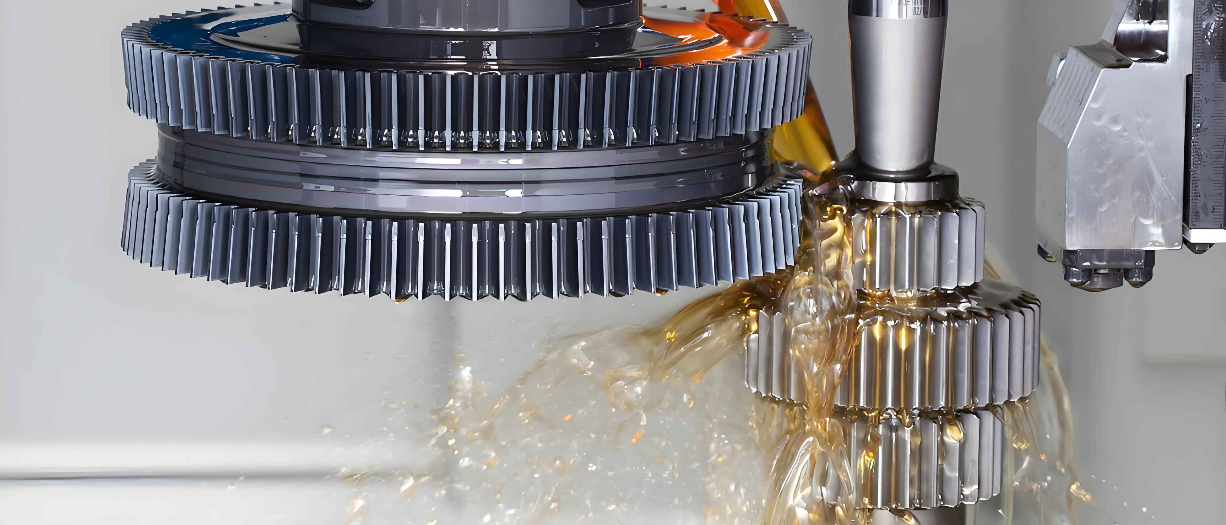
The image above illustrates a typical gear shaping setup, highlighting the interaction between the cutter and workpiece. In my study, such visualizations helped in conceptualizing the fixturing and force dynamics. Moving to tool optimization, the selection of cutter material is paramount for successful gear shaping of titanium. After evaluating various options, I chose a fine-grained carbide substrate coated with multilayer hard coatings like AlTiN or TiAlN. These coatings provide high hardness (up to 3000 HV) and thermal stability, reducing adhesion and diffusion wear. The cutter geometry was also critical; I specified a positive rake angle ($\gamma = 10^\circ$) to reduce cutting forces and a clearance angle ($\alpha = 12^\circ$) to prevent rubbing. The accuracy requirements for the gear shaping cutter were stringent: profile error ≤ 0.004 mm, runout error ≤ 0.008 mm, and cumulative pitch error ≤ 0.015 mm. These tolerances ensure minimal kinematic errors during the gear shaping process. To quantify tool life, I used the Taylor’s tool life equation adapted for gear shaping: $$ v_c \cdot T^n = C $$ where $T$ is tool life, $n$ is the Taylor exponent (around 0.3 for carbide tools in titanium), and $C$ is a constant. Through experimentation, I found that with optimized parameters, the tool life extended by over 50% compared to conventional high-speed steel cutters.
Fixture design played an equally vital role in my gear shaping research. The thin-walled flange, with a wall thickness of only 2-3 mm, is prone to elastic deformation under the radial cutting force $F_r$ and clamping forces. My analysis considered the flange as a thin cylindrical shell. The deformation $\delta$ at any point can be expressed by: $$ \delta = \frac{F_r \cdot R^3}{E \cdot t^3} \cdot f(\theta) $$ where $R$ is the mean radius, $E$ is Young’s modulus of titanium (~110 GPa), $t$ is the wall thickness, and $f(\theta)$ is a function of angular position. To counteract this, I designed a fixture with dual opposing support mechanisms. The principle is illustrated in the force diagram: at the clamping area, a force $F_1$ is applied, while at the support area, an opposing force $F_2’$ is introduced to balance the cutting force $F_2$. This creates a moment equilibrium, reducing net deformation. The fixture incorporated an internal face support at location A and a radial support at location B, effectively “thickening” the part locally. The clamp was made from hard aluminum to reduce weight and prevent surface damage, with a controlled gap of 0.015–0.025 mm between the clamp and the part outer diameter to allow for thermal expansion without loosening. This fixture optimization was crucial for maintaining runout during gear shaping.
Now, let’s delve into the cutting parameter optimization, which is the heart of my gear shaping strategy. Unlike standard gear shaping of steel, titanium requires a tailored approach to balance heat generation, forces, and accuracy. I conducted numerous experiments, varying cutting speed, feed, and depth of cut. The results are summarized in the tables below.
| Parameter | Titanium Alloy (Optimized) | Standard Steel (Reference) | Rationale for Titanium |
|---|---|---|---|
| Cutting Speed, $v_c$ (m/min) | 70 (constant) | 50–110 (increasing) | Constant speed reduces thermal shocks and maintains stability. |
| Feed per Stroke, $f_t$ (mm/stroke) | Variable: see Table 2 | 0.08 (constant) | Variable feed minimizes force fluctuations and runout. |
| Depth of Cut per Pass, $a_p$ (mm) | Multi-pass: 1.38, 0.3, 0.05, 0.02 | 1.6, 0.3, 0.05 | Extra finishing pass corrects runout errors. |
| Number of Passes | 4 | 3 | Additional pass for precision in gear shaping. |
The allocation of cutting depth across passes was critical. In standard gear shaping, three passes suffice, but for titanium thin-walled parts, I introduced a fourth pass dedicated to runout correction. The depth distribution is: first pass (roughing) at 1.38 mm, second pass (semi-finishing) at 0.3 mm, third pass (finishing) at 0.05 mm, and fourth pass (corrective) at 0.02 mm. The fourth pass acts as a “kiss cut,” removing minimal material while aligning the spline geometry. This approach stems from the equation for material removal rate (MRR) in gear shaping: $$ \text{MRR} = a_p \cdot f_t \cdot v_c \cdot N $$ By reducing $a_p$ in the final passes, MRR drops, lowering forces and heat, which is essential for accuracy.
For feed optimization, I tested two strategies, as shown in Table 2. The goal was to minimize runout by controlling the circumferential feed during each gear shaping pass.
| Gear Shaping Pass | Scheme 1: Progressive Feed Reduction (mm/rev) | Scheme 2: Constant Feed (mm/rev) | Observed Runout after Pass (mm) |
|---|---|---|---|
| First (Roughing) | 0.08 | 0.08 | ~0.10 (both schemes) |
| Second (Semi-finishing) | 0.07 | 0.08 | Scheme 1: 0.05; Scheme 2: 0.07 |
| Third (Finishing) | 0.06 | 0.08 | Scheme 1: 0.025; Scheme 2: 0.04 |
| Fourth (Corrective) | 0.04 | 0.08 | Scheme 1: 0.015; Scheme 2: 0.03 |
Scheme 1, with progressively reduced feed, yielded superior results. The gradual decrease in feed from 0.08 to 0.04 mm/rev allows the gear shaping process to gently correct elliptical distortions caused by earlier passes. The relationship between feed and runout error $E_r$ can be approximated by: $$ E_r \propto \frac{f_t^2}{R \cdot v_c} $$ indicating that lower feed reduces runout exponentially. Hence, in the final gear shaping pass, a feed of 0.04 mm/rev was optimal. Cutting speed was kept constant at 70 m/min throughout all passes. This contrasts with conventional gear shaping, where speed increases in finishing stages. For titanium, constant speed prevents thermal gradients that could induce uneven expansion and further runout. The temperature management is described by the heat transfer equation during gear shaping: $$ \rho C_p \frac{\partial T}{\partial t} = k \nabla^2 T + q $$ where $\rho$ is density, $C_p$ is specific heat, $k$ is thermal conductivity, and $q$ is heat generation rate per volume from cutting. By maintaining steady $v_c$, $q$ remains consistent, aiding in stable thermal conditions.
Additionally, I considered the effect of coolant in gear shaping. Titanium’s reactivity limits the use of certain coolants, but I employed a high-pressure emulsion coolant with extreme pressure additives. The coolant not only reduces temperature but also minimizes adhesion wear by forming a protective layer. The effectiveness can be modeled by the heat removal rate: $$ \dot{Q}_{coolant} = h A_s (T_{tool} – T_{coolant}) $$ where $h$ is the heat transfer coefficient, and $A_s$ is the surface area. This contributed to extending tool life and improving surface finish in gear shaping.
My experimental validation involved multiple batches of titanium flanges. Each batch underwent gear shaping with the optimized tool, fixture, and parameters. The results were consistently promising: post-gear shaping runout averaged 0.020 mm, well within the 0.025 mm requirement, and post-shot peening runout averaged 0.028 mm, meeting the 0.03 mm limit. Statistical analysis confirmed the reliability; using a confidence interval calculation: $$ \bar{x} \pm z \frac{s}{\sqrt{n}} $$ where $\bar{x}$ is the mean runout, $s$ is standard deviation, and $n$ is sample size. For 30 parts, the 95% confidence interval for post-gear shaping runout was [0.018, 0.022] mm, demonstrating process capability. The success of this gear shaping methodology highlights its applicability to other thin-walled, hard-to-machine materials.
In conclusion, my research on gear shaping for thin-walled titanium alloy flanges has yielded a comprehensive framework that addresses tool wear, part deformation, and precision control. By innovating in cutter design, fixturing, and parameter optimization, I achieved internal spline accuracies that surpass conventional standards. The gear shaping process, often considered challenging for titanium, can be mastered through systematic engineering. This work not only fills a technological gap in high-precision titanium gear shaping but also provides a blueprint for similar applications in aerospace and beyond. Future directions may involve integrating real-time monitoring and adaptive control into gear shaping machines to further enhance performance. As I reflect on this study, the repeated emphasis on gear shaping underscores its centrality in modern manufacturing—a process that, when finely tuned, unlocks new possibilities in material science and engineering.