
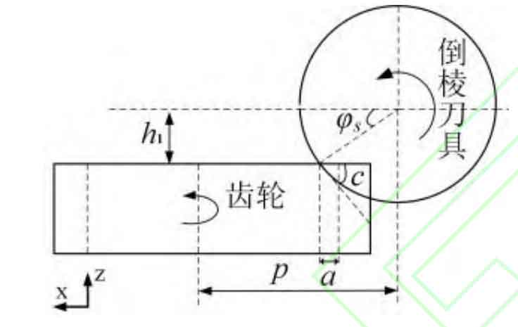
The chamfering of tooth profile is different from the machining of tooth surface. In order to avoid scratching the tooth surface in the chamfering process, it is necessary to adjust the installation position and posture of the cutter. The initial installation position parameters of the tool include center height H1, center distance P and initial inclination φ S (as shown in Fig. 1), where the center height H1 is the height difference between the geometric center of the tool and the upper end face of the cylindrical gear in the z-axis direction, and the initial inclination φ S and chamfering angle c are complementary angles to each other, while the center distance P in the x-axis direction is related to chamfering thickness a and chamfering angle c (initial inclination φ s) And the center height H1, i.e.:

Where HF is the root circle diameter of cylindrical gear.
According to the spatial geometric relationship between the tool and the cylindrical gear, the coordinate system of the tool installation pose is established (as shown in Figure 2), in which the tool installation pose includes the installation pose (installation angle) β) And installation position (installation height h, center distance P, eccentricity w). Establish reference coordinate systems om-xmymzm and o1-x1y1z1, both of which are static coordinate systems. Among them, ZM coincides with the axis of the cylindrical gear, and the origin is at the center of the upper end face of the cylindrical gear; The Z1 axis coincides with the tool axis, and the origin is on the ymomzm plane of the coordinate system om xmymzm; O is the geometric center of the tool.
According to the chamfering parameters and the established installation pose coordinate system, the tool installation pose parameters are calculated. The installation angle of the tool is determined by the spiral rise angle of the tool. The spiral rise angle of the tool is related to the tool parameters, namely:
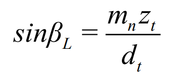
Among them β L is the spiral rising angle of the tool, Mn is the normal surface modulus of the cylindrical gear, ZT is the number of teeth of the hobbing chamfering tool, and DT is the pitch diameter of the tool.
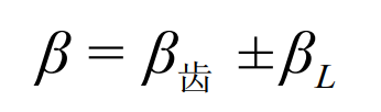
Among them β The tool mounting angle is, β The tooth is the helix angle of cylindrical gear. Mounting angle β It is related to the helix direction and helix angle of the cutter and the processed cylindrical gear. When the helix direction of the chamfering cutter is the same as that of the cylindrical gear, the “-” sign is taken in the formula, and the “+” sign is taken on the contrary.
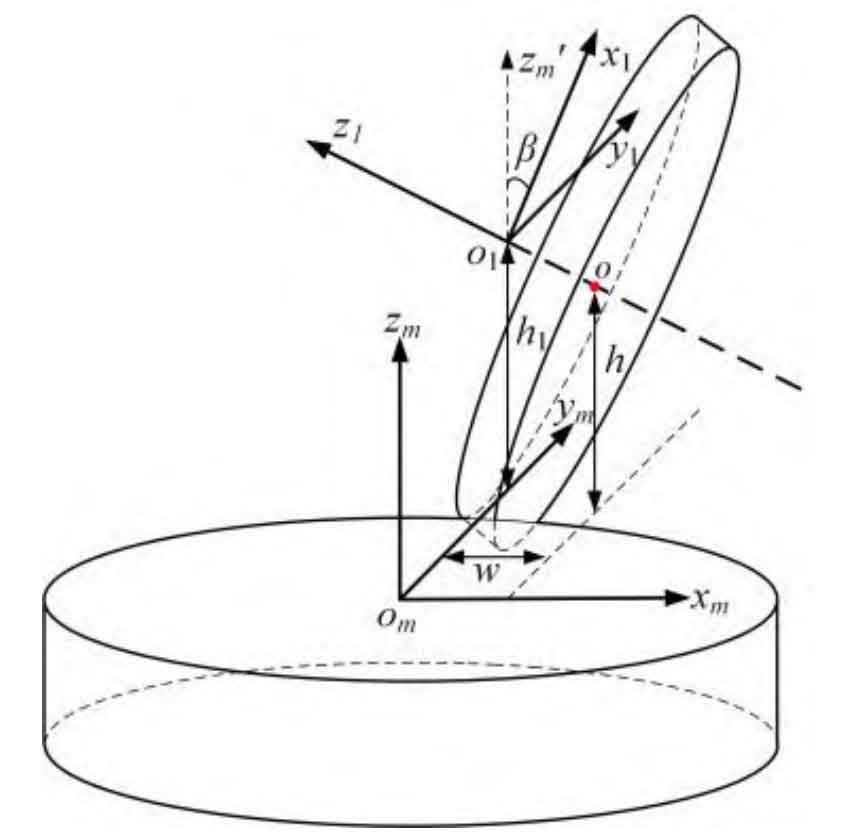
During the chamfering process, the height of the first seamless contact between the rake face of the tool and the upper end face of the cylindrical gear is the tool installation height.
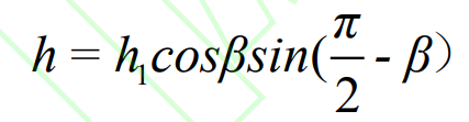
Where h is the installation height of the tool and the distance between the geometric center o point of the tool and the static coordinate system xmomym surface of the cylindrical gear.
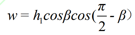
Where W is the eccentricity of the tool and the distance between the geometric center o point of the tool and the cylindrical gear static coordinate system ymomzm surface.