The detailed steps of solving the elliptic boundary and contact line of the instantaneous contact between two tooth surfaces based on numerical iteration are as follows:
Step 1: as shown in Figure 1, the contact point of the two tooth surfaces is point P, n is the normal plane, M is the tangent plane, and l is the rotation projection surface. Taking point P as the center of the circle and the line where the normal vector of point P is located as the axis, a radius (assumed to be r) The minimum value and maximum value can be found in the distance corresponding to all intersecting generatrix for a very small cylinder cutting two meshing tooth surfaces. The minimum value corresponds to the intersection point of two intersecting generatrix and two tooth surfaces, that is, the point on the long axis of the instantaneous contact ellipse on the tooth surface, while the maximum value corresponds to the point on the short axis of the instantaneous contact ellipse. In particular, when the distance between two intersecting generatrix is equal to the elastic deformation δ (δ is generally taken as 0.00635mm, 0.00635mm is converted from 0.00025 inch, which is equal to the diameter of red lead powder coated by traditional rolling inspection; grinding tooth surface is taken as 0.0038mm), the intersection point of two tooth surfaces corresponds to the boundary point of instantaneous contact ellipse.

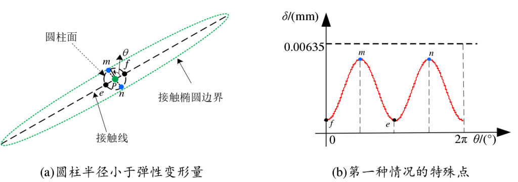
The second step is to increase the value of radius r from 0 until the distance between the two tooth surfaces is greater than the elastic deformation δ. A series of points on the long and short axes of the instantaneous contact ellipse and a series of boundary points of the instantaneous contact ellipse can be obtained. Two maxima and two minima can also be found in the radius of the cylinder corresponding to all boundary points, which correspond to the two endpoints of the major axis and the minor axis of the instantaneous contact ellipse, respectively. When the distance between two tooth surfaces has not reached the elastic deformation amount δ, there will be two minimum points on the long axis, as shown in points E and F in Fig. 2 (a) (b), and two maximum points on the minor axis, as shown by points m and N in Fig. 2 (a) (b); when the distance between two tooth surfaces is greater than the elastic deformation amount δ, points a, B, C, D in Fig. 2 (a) (b) will appear The minimum points correspond to e and f points on the long axis. If all the points obtained are projected onto the rotating projection plane L, the instantaneous contact ellipse boundary and its major axis and minor axis on the rotating projection plane can be obtained when point P contacts.

Step 3: repeat the above steps at each contact point in the whole meshing cycle of the gear, and the part of the area surrounded by these contact ellipses within the effective contact boundary of the tooth surface constitutes the contact mark of the whole tooth surface, which can be used to simulate the gear rolling inspection mark in the design stage, as an effective reference for designing the meshing performance of the gear.
This method only needs to know the equations of two pairs of tooth surfaces and get the contact point of two tooth surfaces when solving the major and minor axes and boundary of the instantaneous contact ellipse of two tooth surfaces. The complex derivation and calculation of tooth surface curvature are avoided, and the instantaneous contact ellipse and instantaneous contact ellipse obtained by this method can be obtained The contact mark can reflect the contact condition of the actual tooth surface.
