
The pursuit of efficient and precise hard-finishing methods for gears has led to the development of various advanced processes. Among these, gear honing, specifically internal gear honing, presents a unique and sophisticated solution. Unlike conventional gear shaving or grinding, internal gear honing operates on the principle of spatial cross-axis internal meshing. In this paper, I will delve into a detailed theoretical foundation for this process, deriving the essential mathematical models and presenting a comprehensive computer-simulated Tooth Contact Analysis (TCA). This analysis provides the crucial theoretical underpinning necessary for the practical application and optimization of internal gear honing.
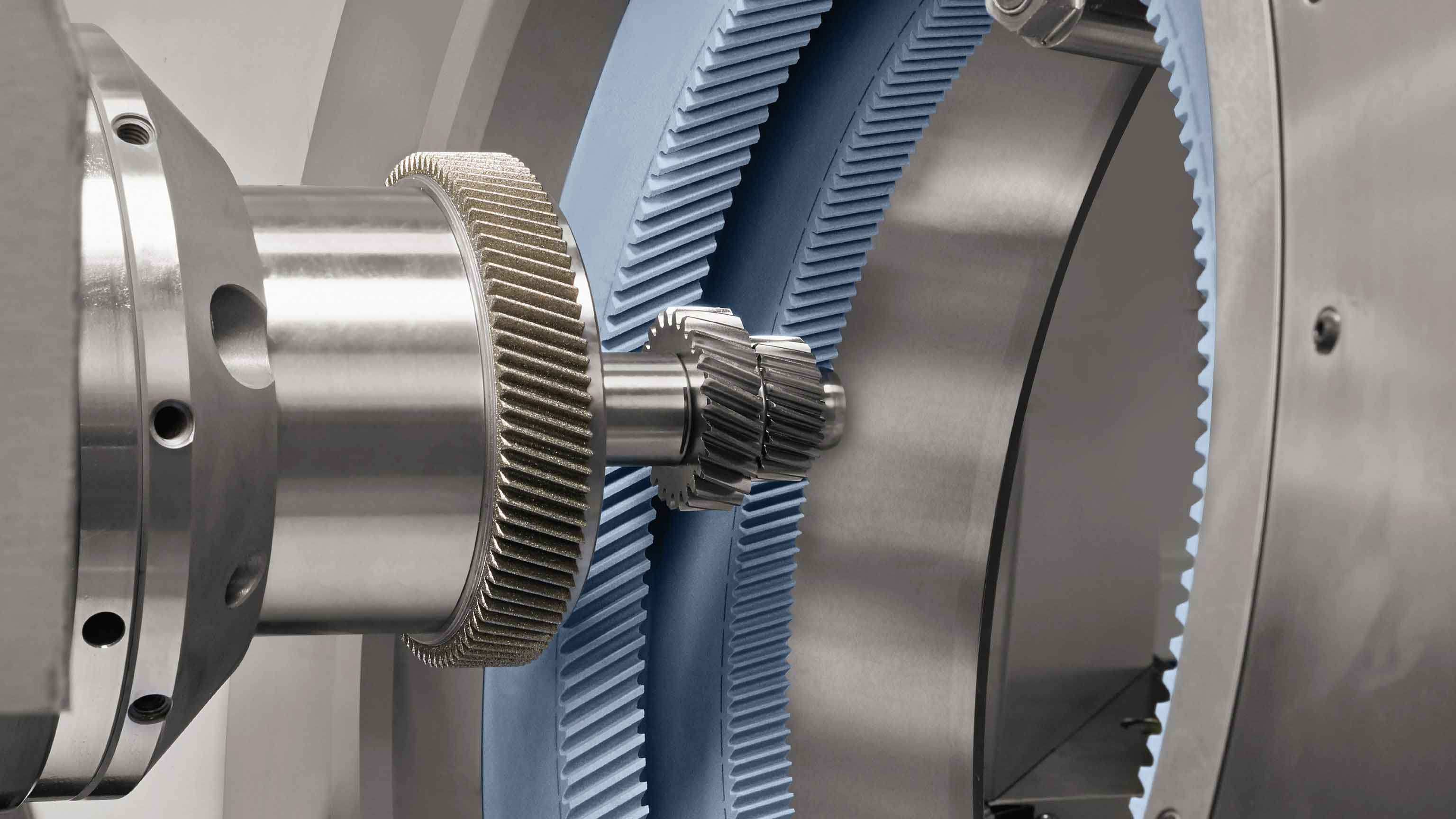
The core principle of internal gear honing involves a two-step enveloping process. First, a diamond or CBN dressing worm, identical to the workpiece gear, is used to generate (or envelope) the tooth surface of an internal honing wheel. Subsequently, this internal honing wheel engages with the hardened workpiece gear in a spatial, cross-axis arrangement to perform the final finishing via a secondary enveloping action. This establishes two critical conditions: the meshing state between the honing wheel and the workpiece is one of spatial crossed axes, and the tooth surface of the internal honing wheel is not a simple involute helicoid but rather the envelope surface of the dressing worm’s involute helicoid.
1. Fundamental Mathematical Model of Internal Gear Honing
The theoretical analysis begins with defining the geometry of the workpiece and establishing the mathematical conditions for meshing between the dressing worm (or workpiece surface) and the generating internal honing wheel.
1.1 Workpiece Tooth Surface Equation
The workpiece tooth surface, an involute helicoid, can be parameterized. As shown in relevant schematics, an involute in the transverse plane is rotated around the gear axis with a simultaneous translational motion along the axis, generating the helicoid. Its equation in coordinate system $S_1(O_1-X_1Y_1Z_1)$, attached to the workpiece, is given by:
$$
\mathbf{r_1} = \begin{bmatrix}
x_1 \\
y_1 \\
z_1
\end{bmatrix} = \begin{bmatrix}
r_b(\cos(\theta + \nu) + \theta \sin(\theta + \nu)) \\
r_b(\sin(\theta + \nu) – \theta \cos(\theta + \nu)) \\
p \theta
\end{bmatrix}
$$
where:
$r_b$ is the base circle radius.
$\theta$ is the involute roll angle, a parameter defining a point on the involute.
$\nu$ is a constant angle, often the involute pressure angle at a standard point.
$p$ is the helix parameter ($p = r_b / \tan\beta_b$, with $\beta_b$ as the base helix angle). For a right-hand helix, $p$ is positive.
1.2 Coordinate Systems and Meshing Equation
The spatial relationship between the internal honing wheel and the workpiece is defined using a set of coordinate systems. Let $S(O-XYZ)$ and $S_p(O_p-X_pY_pZ_p)$ be fixed in space, with their $Z$ and $Z_p$ axes representing the rotation axes of the workpiece and honing wheel, respectively. These axes are crossed at an angle $\Sigma$. The $X$ and $X_p$ axes are collinear, and the shortest distance between the two axes is the center distance $a$. Coordinate systems $S_1(O_1-X_1Y_1Z_1)$ and $S_2(O_2-X_2Y_2Z_2)$ are rigidly connected to the workpiece and the honing wheel. When the workpiece rotates by angle $\varphi_1$, the honing wheel rotates by $\varphi_2$, with the ratio $i_{21} = \varphi_2 / \varphi_1 = \omega_2 / \omega_1$.
The fundamental meshing condition requires that the relative velocity vector at a point of contact between two surfaces is perpendicular to their common normal vector. This is expressed by the equation of meshing:
$$
\mathbf{n} \cdot \mathbf{v}^{(12)} = 0
$$
where $\mathbf{n}$ is the common unit normal vector to the surfaces, and $\mathbf{v}^{(12)}$ is the relative velocity of surface 1 (workpiece) with respect to surface 2 (honing wheel). Applying this condition to the workpiece surface $\mathbf{r_1}(\theta, \nu)$ and the transformation from $S_1$ to $S_2$ via the fixed systems, we derive the meshing equation specific to the internal gear honing configuration. After significant algebraic manipulation involving the components of $\mathbf{n}$ and $\mathbf{v}^{(12)}$, the meshing equation can be solved for one parameter, for instance, $\theta$, in terms of the other and the rotation angle $\varphi_1$:
$$
\theta = \Theta(\nu, \varphi_1)
$$
For a right-hand honing wheel finishing a right-hand gear, a specific form of this equation is:
$$
\theta = \frac{1}{p \sin\Sigma} \left[ (a – \frac{r_b}{\cos\beta_b} \cos\Sigma ) p + \frac{r_b \sin(\nu+\varphi_1)}{\cos\beta_b} \left( \frac{1}{i_{21}} – \cos\Sigma \right) \right]
$$
This equation is pivotal as it defines which points on the workpiece surface are in contact with the honing wheel surface for a given wheel position $\varphi_1$.
1.3 Instantaneous Contact Line and Honing Wheel Tooth Surface
For a fixed angle $\varphi_1$, the set of points on the workpiece surface that satisfy the meshing equation form a line, known as the instantaneous contact line. Its equation is obtained by combining the surface equation $\mathbf{r_1}(\theta, \nu)$ with the meshing condition $\theta = \Theta(\nu, \varphi_1)$:
$$
\mathbf{r_1}^{contact}(\nu; \varphi_1) = \mathbf{r_1}(\Theta(\nu, \varphi_1), \nu)
$$
The tooth surface of the internal honing wheel is the family of these contact lines transformed into the honing wheel’s coordinate system $S_2$. Applying the coordinate transformation $\mathbf{r_2} = M_{21}(\varphi_1, \varphi_2) \mathbf{r_1}$ yields the honing wheel tooth surface equation:
$$
\mathbf{r_2}(\nu, \varphi_1) = \begin{bmatrix}
x_2(\nu, \varphi_1) \\
y_2(\nu, \varphi_1) \\
z_2(\nu, \varphi_1)
\end{bmatrix}
$$
where the transformation matrix $M_{21}$ incorporates rotations by $\varphi_1$ and $\varphi_2$ about the respective axes, the center distance $a$, and the shaft angle $\Sigma$. The explicit, lengthy form confirms that the honing wheel surface is a complex envelope, not a standard helicoid.
| Entity | Mathematical Representation | Key Variables |
|---|---|---|
| Workpiece Surface | $\mathbf{r_1} = [r_b(\cos(\theta+\nu)+\theta\sin(\theta+\nu)),\, r_b(\sin(\theta+\nu)-\theta\cos(\theta+\nu)),\, p\theta]^T$ | $\theta, \nu$: Parameters; $r_b, p$: Geometry |
| Meshing Equation | $\theta = \frac{1}{p\sin\Sigma}\left[ (a – \frac{r_b}{\cos\beta_b}\cos\Sigma)p + \frac{r_b\sin(\nu+\varphi_1)}{\cos\beta_b}(\frac{1}{i_{21}}-\cos\Sigma) \right]$ | $\varphi_1$: Workpiece rotation; $\Sigma$: Shaft angle; $a, i_{21}$: Kinematics |
| Instantaneous Contact Line | $\mathbf{r_1}^{contact}(\nu) = \mathbf{r_1}(\Theta(\nu, \varphi_1), \nu)$ | Defined for a constant $\varphi_1$ |
| Honing Wheel Surface | $\mathbf{r_2}(\nu, \varphi_1) = M_{21}(\varphi_1, \varphi_2) \cdot \mathbf{r_1}(\Theta(\nu, \varphi_1), \nu)$ | Envelope of contact lines in $S_2$ |
2. Analysis of the Contact Zone and Meshing Boundaries
A critical aspect of gear honing theory is understanding the extent of contact on the workpiece tooth flank. The family of instantaneous contact lines may have an envelope within the active tooth surface, known as the meshing boundary or limit line. This line divides the tooth into a region that makes contact during the honing cycle and a region that does not.
2.1 Equation of the Meshing Boundary Line
The meshing boundary line on the workpiece is found by solving the system comprising the meshing equation and its derivative with respect to the motion parameter $\varphi_1$:
$$
\Phi(\theta, \nu, \varphi_1) = 0 \quad \text{and} \quad \frac{\partial \Phi(\theta, \nu, \varphi_1)}{\partial \varphi_1} = 0
$$
This leads to a condition that can often be expressed in terms of the parameters. For the internal gear honing model, it results in a specific relationship for $\theta$ at the boundary:
$$
\theta_{boundary} = \frac{1}{p \sin\Sigma} \left[ p(r_b – a \cos\beta_b) \pm \sqrt{\Delta} \right]
$$
where $\Delta$ is a discriminant given by:
$$
\Delta = \left[ \left( \frac{1}{i_{21}} – \cos\Sigma \right) \frac{p r_b}{\sin\Sigma} \right]^2 – (a \cos\beta_b \sin\Sigma)^2
$$
Substituting $\theta_{boundary}$ back into the workpiece surface equation $\mathbf{r_1}(\theta, \nu)$ yields the meshing boundary line. The discriminant $\Delta$ is crucial:
- If $\Delta > 0$, there are two distinct meshing boundary lines on the tooth surface.
- If $\Delta = 0$, the two lines coincide into a single boundary.
- If $\Delta < 0$, there is no meshing boundary line within the mathematical surface, implying the entire theoretical flank could be contacted.
2.2 Criterion for Effective Honing and Shaft Angle Selection
For effective gear honing, the entire functional tooth flank must be processed. Therefore, the meshing boundary line(s), if they exist, must lie outside the active profile (e.g., within the fillet or above the tip). The most favorable condition for comprehensive honing is $\Delta < 0$. Setting $\Delta = 0$ provides the limiting condition for the shaft angle $\Sigma$. This leads to a critical shaft angle $\Sigma_{crit}$:
$$
\cos\Sigma_{crit} = \frac{1}{i_{21}} – \frac{a \cos\beta_b \sin^2\Sigma_{crit}}{p r_b}
$$
Given that $i_{21} = z_w / z_h$ (where $z_w$ and $z_h$ are tooth numbers of workpiece and honing wheel) and $p = m_n z_w / (2 \tan\beta_b)$ (for a standard gear, with $m_n$ as normal module), a practical criterion emerges. For successful internal gear honing:
- For helical gears: The actual shaft angle $\Sigma$ must satisfy $|\beta_w – \beta_h| < \Sigma < \Sigma_{crit}$, where $\beta_w$ and $\beta_h$ are the workpiece and honing wheel helix angles. Often, choosing $\Sigma = |\beta_w – \beta_h|$ (the “parallel-axes” condition for helical gears) inherently satisfies $\Delta < 0$ for common geometries.
- For spur gears ($\beta_w=0$): The shaft angle $\Sigma$ must be positive (crossed axes) but less than $\Sigma_{crit}$: $0 < \Sigma < \Sigma_{crit}$.
The center distance $a$ and ratio $i_{21}$ for nominal meshing without backlash are calculated as:
$$
a = \frac{m_n}{2 \cos\beta} (z_h – z_w) \quad \text{and} \quad i_{21} = \frac{z_w}{z_h}
$$
| Condition of $\Delta$ | Meshing Boundaries on Workpiece | Implication for Gear Honing |
|---|---|---|
| $\Delta > 0$ | Two distinct lines exist. | Potential for incomplete honing in the central region. Undesirable. |
| $\Delta = 0$ | A single boundary line exists. | Limiting case. Contact covers entire flank up to this line. |
| $\Delta < 0$ | No boundary lines on the active flank. | Ideal. Theoretically, entire flank can be contacted during the honing cycle. |
Design Rule: Select shaft angle $\Sigma$ and center distance $a$ to ensure $\Delta \le 0$ for the given workpiece and honing wheel geometry.
3. Computer Simulation for Tooth Contact Analysis (TCA)
To visualize the contact pattern and validate the theory, computer-simulated Tooth Contact Analysis is indispensable. I developed a simulation program based on the derived equations to model the gear honing process.
3.1 Simulation Methodology and Flow
The simulation follows a systematic flow:
- Input Parameters: Define workpiece and honing wheel geometry (module, tooth numbers, pressure angle, helix angles, face width).
- Calculate Derived Geometry: Compute base radii, helix parameters, nominal center distance, and transmission ratio.
- Select Process Parameters: Choose honing wheel helix angle $\beta_h$ and shaft angle $\Sigma$.
- Compute Meshing Data: For discrete values of the workpiece rotation angle $\varphi_1$ over one mesh cycle:
- Solve the meshing equation $\theta = \Theta(\nu, \varphi_1)$ for a range of the profile parameter $\nu$ spanning the tooth flank.
- Calculate the corresponding points on the workpiece contact line using $\mathbf{r_1}^{contact}(\nu)$.
- Transform these points to a radial projection plane for visualization.
- Plot and Analyze: Plot all instantaneous contact lines for successive $\varphi_1$ values on the tooth flank projection. Analyze the coverage and density of the contact pattern.
| Component | Parameter | Case 1: Helical Gear | Case 2: Spur Gear |
|---|---|---|---|
| Workpiece | Normal Module, $m_n$ | 2.5 mm | 2.5 mm |
| Number of Teeth, $z_w$ | 25 | 30 | |
| Pressure Angle, $\alpha_n$ | 20° | 20° | |
| Helix Angle, $\beta_w$ | 30° (Right Hand) | 0° | |
| Face Width | 10 mm | 10 mm | |
| Honing Wheel | Number of Teeth, $z_h$ | 97 | 97 |
| Helix Angle, $\beta_h$ | 17.43° (Right Hand)* | 17.43°* | |
| Face Width | 20 / 40 mm | 20 / 40 mm | |
| Shaft Angle, $\Sigma$ | 12.57° (=$|\beta_w-\beta_h|$) | 17.43° (=$|\beta_h|$) | |
| Nominal Center Distance, $a$ | Calculated from formula | Calculated from formula |
*The honing wheel helix angle is a design choice influencing contact patterns and cutting kinematics.
3.2 Simulation Results and Interpretation
The TCA simulation for the two cases yields clear graphical outputs of the contact lines on the workpiece tooth flank.
For the helical gear case ($\Sigma = |30° – 17.43°| = 12.57°$): The computed discriminant $\Delta$ is negative. The simulated contact lines form a dense, uniform network that covers the entire tooth flank from root to tip and heel to toe. This confirms that with $\Sigma = |\beta_w – \beta_h|$, the condition $\Delta < 0$ is met, resulting in no meshing boundaries and full flank contact. The pattern is diagonal across the tooth face, characteristic of crossed-axis helical meshing.
For the spur gear case ($\Sigma = 17.43°$): The simulation also shows a full coverage of the tooth flank by the family of contact lines. The pattern is more vertical compared to the helical case but still slightly diagonal due to the crossed axes. The analysis confirms that for the chosen $\Sigma$, the entire functional profile is engaged during the gear honing cycle.
These simulation results visually validate the theoretical conclusion: by appropriately selecting the shaft angle $\Sigma$ (typically equal to the absolute difference of helix angles for helical gears), the meshing boundary is eliminated, allowing the internal gear honing process to finish the complete tooth flank. In practice, an axial reciprocating motion is superimposed to average out machine errors and improve surface finish, but the fundamental contact geometry is defined by this static TCA.
4. Practical Implications and Process Design Considerations
The theoretical framework and TCA simulation provide direct guidance for the practical application of internal gear honing.
1. Honing Wheel Design: The honing wheel is not a standard gear. Its tooth surface is the envelope of the dressing worm. Therefore, the dressing process (using a worm matching the workpiece) is critical to accurately generate this complex surface. The wheel’s helix angle $\beta_h$ is a free design parameter that, together with the workpiece helix angle $\beta_w$, determines the required shaft angle $\Sigma$.
2. Kinematic Setup: The primary machine settings are the center distance $a$ and the shaft angle $\Sigma$. $a$ is set for nominal meshing without backlash. $\Sigma$ should be set to $|\beta_w – \beta_h|$ for helical gears to achieve full flank contact ($\Delta < 0$). Deviating from this value requires checking the $\Delta < 0$ condition to avoid creating meshing boundaries on the active flank.
3. Contact Pattern and Error Correction: The TCA simulation predicts the nominal contact pattern. In reality, misalignments (e.g., axis non-parallelism, center distance error) will shift and distort this pattern. The gear honing process’s inherent averaging action can correct some errors, but the TCA model can be extended to simulate the effects of such errors, aiding in process troubleshooting and tolerance allocation.
4. Advantages of the Internal Honing Configuration: The internal meshing arrangement offers a high degree of conformity between the honing wheel and the workpiece, allowing multiple teeth to be in contact simultaneously. This distributes the honing forces, reduces specific pressure, and can lead to a more stable process and better surface integrity compared to some external gear finishing methods.
| Parameter | Theoretical Influence | Practical Design Consideration |
|---|---|---|
| Shaft Angle ($\Sigma$) | Directly controls the discriminant $\Delta$. Determines existence of meshing boundaries. | Set $\Sigma = |\beta_w – \beta_h|$ for helical gears. For spur gears, choose a small positive angle (< $\Sigma_{crit}$). |
| Honing Wheel Helix Angle ($\beta_h$) | Affects $\Sigma$, contact line angle, and cutting velocity components. | A design variable. Can be chosen to optimize contact pattern, minimize forces, or match machine capability. |
| Center Distance ($a$) | Affects the meshing equation and contact pressure. | Set precisely for nominal no-backlash meshing. May be adjusted slightly for size control. |
| Transmission Ratio ($i_{21}=z_w/z_h$) | Appears in the meshing equation. Affects the relative rolling/sliding motion. | Determined by tooth counts. A large $z_h$ provides more cutting edges and smoother action. |
| Workpiece Helix Angle ($\beta_w$) | Defines the workpiece geometry and, with $\beta_h$, the optimal $\Sigma$. | Given by the part design. Process must be configured to suit it. |
5. Conclusion
In this comprehensive analysis, I have established a rigorous theoretical foundation for the internal gear honing process. By applying the principles of spatial gearing and envelope theory, I derived the fundamental equations governing the process: the workpiece involute helicoid surface, the meshing condition leading to the contact lines, and the resulting complex envelope surface of the internal honing wheel. A pivotal finding is the derivation of the meshing boundary condition, characterized by the discriminant $\Delta$, which provides a clear mathematical criterion for selecting the shaft angle $\Sigma$ to ensure complete tooth flank coverage. The rule $\Sigma = |\beta_w – \beta_h|$ for helical gears emerges as a key design guideline to achieve the ideal condition of $\Delta < 0$.
The computer-simulated Tooth Contact Analysis, based on these equations, serves as a powerful virtual tool. It visually confirms the theoretical predictions, demonstrating that with correct parameter selection, the instantaneous contact lines from the gear honing cycle indeed blanket the entire active tooth surface. This validates the feasibility of the process for precision finishing.
The significance of this theoretical work is that it moves internal gear honing from an empirical practice to a precisely engineerable process. It provides the necessary framework for:
- Accurate design and manufacture of the honing wheel via the dressing process.
- Optimal machine setup (shaft angle, center distance).
- Prediction and analysis of contact patterns.
- Troubleshooting geometry-related issues.
As the enabling technology—high-precision diamond or CBN dressing tools—becomes more accessible, the internal gear honing process, supported by this solid theoretical and simulative analysis, is poised for broader adoption in high-volume, precision hard-finishing of gears. Future research can build upon this model to incorporate dynamic effects, thermal influences, and the microscopic material removal mechanisms to create a fully integrated digital twin of the gear honing process.