
Chapter 1: Definition and Basic Concepts of Helical Gears
Helical gears are a type of mechanical component commonly used in machinery and mechanical systems to transmit power and motion between rotating shafts. They consist of two or more gears that mesh with each other and work together to transfer rotational motion and torque.
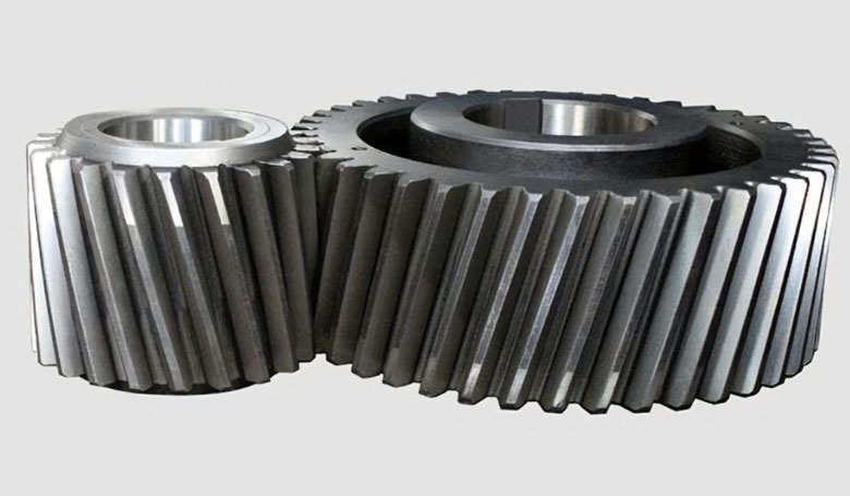
The key characteristic of helical gears is that the teeth on the gear’s cylindrical surface are not arranged parallel to the axis of rotation, as in the case of spur gears, but instead, they are set at an angle to the axis. This angle is known as the helix angle. Because of this helical arrangement, the teeth engage gradually and smoothly, resulting in a more gradual and quieter operation compared to spur gears.
Some important concepts related to helical gears include:
- Helix Angle: As mentioned earlier, the helix angle is the angle between the gear’s tooth trace and the gear axis. This angle affects the smoothness of engagement, load distribution, and axial thrust.
- Direction of Helix: Helical gears can have right-hand or left-hand helix directions, based on the direction in which the teeth wrap around the gear. In a pair of meshing helical gears, both gears must have the same helix direction.
- Axial Thrust: Due to the helical angle, helical gears generate an axial thrust force along the axis of rotation. This axial force needs to be considered and properly managed to prevent unwanted movement of the gears along the axis.
- Contact Pattern: The contact pattern is the area on the tooth where the gears actually make contact during meshing. It’s important for this pattern to be properly aligned and distributed across the tooth width to ensure even load distribution and prevent premature wear.
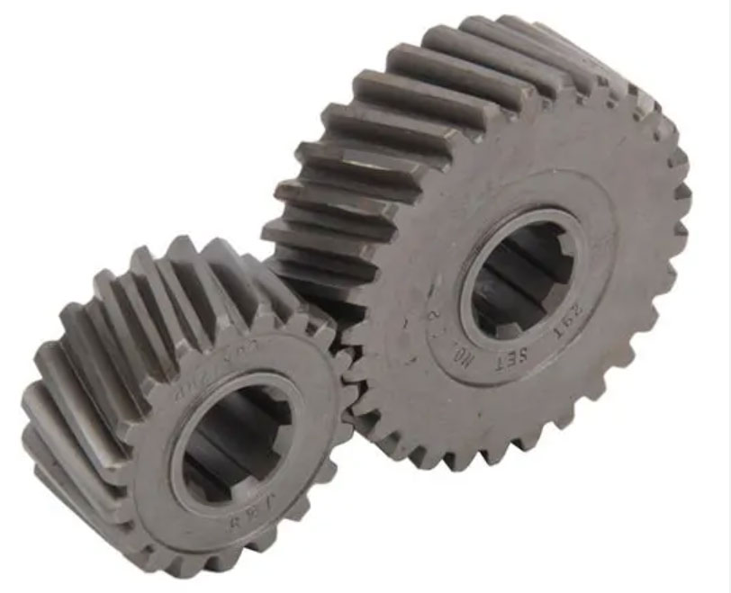
- Gear Ratio: The gear ratio of a pair of helical gears is determined by the number of teeth on each gear. It defines the relationship between the rotational speeds and torques of the input and output shafts.
- Efficiency and Load Distribution: The helical arrangement of teeth results in multiple teeth being in contact at the same time, distributing the load more evenly and increasing efficiency compared to spur gears.
- Manufacturing and Assembly: Helical gears are more complex to manufacture and assemble than spur gears due to the helical angle. Precise manufacturing is crucial to ensure smooth and efficient operation.
- Noise Reduction: The gradual engagement of helical gears helps reduce noise and vibration compared to the sudden engagement of spur gears. This is particularly beneficial for applications requiring quiet operation.
In summary, helical gears are an essential component in many mechanical systems, providing smooth and efficient power transmission while minimizing noise and wear. Their helical tooth arrangement sets them apart from other types of gears and offers advantages in terms of load distribution and operation.
Chapter 2: The Composition of Helical Gears
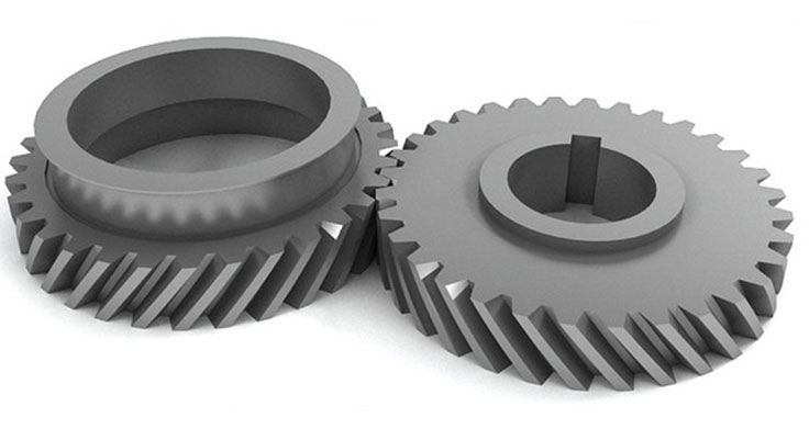
The composition of helical gears includes various components that work together to facilitate power transmission and motion. These components contribute to the functionality and efficiency of the gears. Here’s a breakdown of the main components of helical gears:
- Gear Tooth Surface: The gear tooth surface is the outer curved surface of the gear’s teeth. In helical gears, these teeth are cut at an angle to the gear axis, forming a helix shape. The tooth profile and helix angle are crucial in determining how the gears mesh and transmit motion smoothly.
- Gear Shaft: The gear shaft is the central cylindrical rod of the gear that rotates as a result of power being transmitted through the meshing gears. The shaft is typically supported by bearings at both ends to reduce friction and ensure smooth rotation.
- Gear Pitch: Gear pitch refers to the distance between corresponding points on adjacent teeth. It can be measured in various ways, such as diametral pitch, circular pitch, or module, depending on the system of measurement used. The pitch affects the gear’s size, the number of teeth, and its compatibility with other gears.
- Helix Angle: The helix angle is the angle formed between the gear’s tooth trace and its axis. This angle determines the degree of the helical arrangement of teeth and significantly influences the gear’s performance characteristics, such as load distribution and noise level.
- Gear Hub: The gear hub is the central part of the gear that surrounds the shaft. It provides support and rigidity to the gear teeth, and it is usually where the gear is attached to the rotating shaft.
- Gear Teeth: The gear teeth are the most essential part of the gear. They engage with the teeth of other gears in the meshing arrangement to transmit motion and torque. The shape, profile, and angle of the teeth are critical factors in ensuring smooth and efficient operation.
- Backlash: Backlash is the small amount of play or clearance between the teeth of meshing gears. Properly controlling backlash is important for minimizing vibrations and ensuring accurate motion transfer.
- Bearings: Bearings are essential components that support the gear shaft and reduce friction during rotation. They help maintain smooth and efficient motion transfer while minimizing wear and heat generation.
- Mounting Features: Helical gears often have specific features on their surfaces for mounting and connecting with other components in the system. These features can include holes, keyways, splines, or other attachments that ensure secure positioning and power transmission.
- Lubrication: Proper lubrication is crucial to reduce friction, wear, and heat buildup between the meshing gears. Lubricants help maintain efficient operation and extend the gears’ lifespan.
- Housing or Enclosure: In many applications, helical gears are housed within an enclosure or gearbox. The housing provides protection, helps contain lubricants, and maintains the gears’ alignment and position.
The successful operation of helical gears depends on the precise design, manufacturing, and assembly of these components. Each part plays a critical role in ensuring the gears function smoothly, transmit power effectively, and endure the stresses of operation.
Chapter 3: The Tooth Surface Meshing of Helical Gears:
Helical gears do indeed transmit rotational motion from one shaft to another through the meshing of their tooth surfaces. The engagement of the helical teeth on the two gears allows for the transfer of torque and rotational movement between the shafts.
Because of the helical arrangement of the teeth, the engagement begins gradually and smoothly as the teeth come into contact, and the contact between the teeth shifts gradually across the width of the tooth face as the gears rotate. This gradual engagement and the larger contact area compared to straight-tooth gears like spur gears contribute to smoother motion transmission and reduced noise and vibration.
- Tooth Meshing: When the teeth of two helical gears come into contact, they mesh together, creating a mechanical linkage between the two gears.
- Torque Transfer: As one gear is rotated, its teeth push against the teeth of the other gear, creating a force that transfers torque from one gear to the other. This torque transfer is what allows rotational motion to be transmitted between the two shafts.
- Gradual Engagement: The helical arrangement of the teeth ensures that contact is made gradually and progressively across the width of the tooth face, which reduces the impact forces and results in smoother motion transmission.
- Axial Thrust: The helix angle of the teeth introduces an axial component to the force between the meshing gears. This axial thrust must be considered and managed to prevent unwanted axial movement of the gears along the shaft.
In summary, the meshing of the tooth surfaces of helical gears is a fundamental mechanism that enables the transmission of rotational motion and torque between two shafts. The helical arrangement of the teeth contributes to smoother engagement and motion transfer compared to other gear types, making helical gears suitable for applications where precision, efficiency, and reduced noise are important.
Chapter 4: The Transmission Characteristics of Helical Gears
Helical gears are a type of mechanical transmission system that consists of two toothed wheels with helically shaped teeth. They are commonly used in situations where a change in the direction of rotation and efficient power transmission between non-parallel axes is required. Here are some more details about the transmission characteristics of helical gears:
- Cross-Axis Transmission: Helical gears can transmit power between non-parallel shafts. This ability is particularly useful when the input and output shafts need to be oriented at different angles. The helical angle of the teeth enables smooth engagement and reduces the risk of noise and vibration compared to straight-toothed gears.
- Transmission Ratio: The transmission ratio of helical gears depends on two main factors: the number of teeth on each gear and the module (modulus) of the gears. The module is a measure of the size of the gear teeth and is related to the pitch diameter. The transmission ratio determines how the rotational speed and torque are transferred between the gears. In a simple scenario, where the gears have a 1:1 transmission ratio, the speed remains the same, and torque is transferred as-is. In other cases, where the gears have different numbers of teeth, the speed and torque relationship changes according to the gear ratio.
- Speed Ratio and Torque Changes: The speed ratio between helical gears is inversely proportional to the gear ratio. If the driving gear (gear with power input) has more teeth than the driven gear (gear with power output), the speed of the driven gear will be higher, and vice versa. However, due to the helical angle of the teeth, the engagement between the gears is smoother, resulting in reduced noise and vibration compared to straight-toothed gears. The torque changes depend on the gear ratio as well. When the input and output speeds differ, the torque is inversely proportional to the speed change. This means that if the speed increases, the torque decreases, and vice versa.
- Efficiency and Load Distribution: Helical gears have the advantage of distributing the load over a larger area of gear teeth compared to spur gears (gears with straight teeth). This helps in reducing wear and increasing the overall efficiency of the gear transmission system.
- Axial Thrust: One challenge with helical gears is the axial thrust generated due to the helical angle of the teeth. This thrust can cause axial movement of the gears along the shafts. To counteract this, various methods, such as using double helical gears or thrust bearings, are employed.
In summary, helical gears are versatile transmission components that are widely used in various mechanical systems. They enable the transfer of power between non-parallel axes while providing benefits such as smooth engagement, load distribution, and the ability to change rotational direction. The transmission ratio, speed ratio, and torque changes in a helical gear system are influenced by factors like the number of teeth and the module of the gears.
Chapter 5: Design and Analysis of Helical Gears
Designing and analyzing helical gears involves several important steps to ensure optimal performance and durability. Here’s a comprehensive overview of the process:
1. Gear Design:
a. Selection of Parameters:
- Tooth Number (N): Determine the number of teeth based on the desired gear ratio and size constraints.
- Module (m): Choose a suitable module that balances strength and size.
- Pressure Angle (α): Typically 20° or 14.5°. A lower angle reduces contact stress but increases axial thrust.
- Helix Angle (β): Angle between the tooth helix and the gear axis. It affects tooth load sharing and axial thrust.
- Face Width (b): Width of the gear face that affects load distribution.
- Pitch Diameter (d): Calculate using the formula d = N/m.
b. Tooth Profile:
- Use involute tooth profile for smooth and efficient meshing.
- Design the involute profile based on the selected pressure angle and module.
c. Helix Angle and Hand:
- Right-hand helical gears are most common, but left-hand gears are also used in specific applications.
- Helix angle affects the amount of tooth engagement and axial thrust.
2. Gear Analysis:
a. Angular Velocity and Torque:
- Use the gear ratio to calculate angular velocity and torque between the driver and driven gears.
- Angular velocity ratio: ω₁ / ω₂ = N₂ / N₁
- Torque ratio: T₁ / T₂ = ω₂ / ω₁ = N₂ / N₁
b. Efficiency:
- Calculate gear efficiency to assess power losses due to friction and meshing.
- Efficiency = (Output Power / Input Power) * 100
c. Tooth Contact Fatigue:
- Evaluate the gear pair’s ability to withstand repeated loading without failure.
- Calculate contact stress using Hertzian contact theory.
- Use dynamic factors to account for helix angle effects and load distribution.
d. Bending Strength:
- Ensure the gear teeth can handle bending loads without failure.
- Calculate bending stress using the Lewis equation.
- Check against permissible stress limits for the chosen material.
e. Axial Thrust:
- Calculate axial thrust due to helical gears’ inclination.
- Use thrust bearings if excessive axial load is generated.
f. Load Distribution:
- Analyze load distribution along the face width considering the helical angle.
- Uniform load distribution leads to increased durability.
3. Material Selection and Heat Treatment:
- Choose appropriate materials based on strength, wear resistance, and durability requirements.
- Perform heat treatment processes (carburizing, quenching, tempering) to enhance gear properties.
4. Lubrication:
- Adequate lubrication is crucial for reducing wear and friction.
- Select appropriate lubricants based on operating conditions.
5. Tolerance and Manufacturing:
- Consider manufacturing tolerances for accurate gear production.
- Gear cutting methods include hobbing, shaping, and grinding.
6. Simulation and Validation:
- Use computer-aided design (CAD) software for simulation and visualization.
- Validate the design using Finite Element Analysis (FEA) and gear design software.
7. Testing and Inspection:
- Perform gear testing to verify performance under real-world conditions.
- Inspect gear teeth for manufacturing defects and quality control.
Remember that designing and analyzing helical gears is a complex process that requires a deep understanding of mechanical engineering principles. It’s essential to collaborate with experienced engineers and use specialized software for accurate simulations and analyses.
Chapter 6: The Application Field of Helical Gears
Helical gears find applications in a wide range of industries and mechanical systems due to their ability to efficiently transmit power and motion while offering benefits like smoother engagement and load distribution. Here are some specific application fields where helical gears are commonly used:
- Automotive Industry: Helical gears are extensively used in automotive transmissions, both manual and automatic. They help transfer power from the engine to the wheels while providing smooth gear shifts and reduced noise compared to straight-toothed gears. They’re found in gearboxes, differentials, and other drivetrain components.
- Industrial Machinery: Helical gears play a crucial role in various industrial machines, such as manufacturing equipment, conveyors, pumps, and compressors. Their ability to handle high loads and transmit power efficiently makes them suitable for heavy-duty applications.
- Aerospace and Aviation: Helical gears are used in aircraft engines, landing gear systems, and other aerospace applications. They help transfer power and motion within complex systems while maintaining reliability and reducing vibration and noise.
- Marine Applications: Helical gears are employed in marine propulsion systems, steering mechanisms, and winches on ships and boats. Their ability to handle varying loads and provide smooth operation is beneficial in maritime environments.
- Power Generation: Helical gears are used in power generation equipment like generators, turbines, and wind turbines. They assist in transferring rotational energy into electrical energy efficiently.
- Construction Machinery: Helical gears are found in construction equipment such as cranes, excavators, and bulldozers. These gears can handle the heavy loads and rugged conditions commonly encountered in construction sites.
- Mining Equipment: Helical gears are used in mining machinery like crushers, conveyors, and drilling equipment. Their durability and load-bearing capacity make them suitable for the demanding conditions in the mining industry.
- Railway Systems: Helical gears are used in railway locomotives and rolling stock for power transmission between wheels and axles. Their smooth engagement and load-handling capabilities are crucial for reliable train operation.
- Robotics: In robotics, helical gears are often used in robotic arms, joints, and other motion systems. They provide precise motion control and can handle the dynamic loads associated with robotic movements.
- Textile Industry: Helical gears are used in textile machinery for processes such as spinning, weaving, and dyeing. They ensure smooth motion and precise control in these manufacturing processes.
- Oil and Gas Industry: Helical gears are employed in drilling rigs, pumps, and compressors in the oil and gas sector. They can handle the high torque and heavy loads required in these applications.
- Food and Beverage Industry: Helical gears can be found in food processing and packaging equipment where precise and hygienic motion control is essential.
These examples highlight the versatility and importance of helical gears in various industries. Their ability to efficiently transmit power, handle varying loads, and provide smoother operation makes them a fundamental component in many mechanical systems.
Chapter 7: Maintenance and Lubrication of Helical Gears
Proper maintenance and lubrication are crucial for ensuring the longevity and efficient operation of helical gear transmissions. Here’s a breakdown of the key aspects of maintenance and lubrication for helical gears:
1. Regular Inspection:
Regular inspections help identify wear, damage, or any issues that might compromise gear performance. Some important points to consider:
- Tooth Wear: Check for signs of wear on the tooth surfaces, including pitting, scoring, and abrasion. Excessive wear could lead to decreased performance and potential failure.
- Backlash: Measure the backlash (clearance between gear teeth) to ensure it’s within acceptable limits. Excessive backlash can cause noise, vibration, and poor gear meshing.
- Axial Movement: Inspect for axial movement of gears, as it can impact gear engagement and load distribution.
- Lubrication Condition: Assess the condition of the lubricant, looking for contamination, degradation, or insufficient levels.
2. Lubrication:
Proper lubrication is essential for minimizing friction, wear, and heat generation in helical gears. Consider the following points for effective lubrication:
- Lubricant Selection: Choose a high-quality lubricant with the right viscosity, additives, and properties suitable for the gear’s operating conditions.
- Oil Bath or Splash Lubrication: Helical gears are often lubricated using an oil bath or splash method, where the gears are partially submerged in a lubricating oil pool. The gears’ rotation helps distribute the oil to critical areas.
- Forced Lubrication: In some cases, forced lubrication systems, like pumps and nozzles, might be necessary to ensure adequate lubrication at high speeds or heavy loads.
- Lubrication Frequency: Follow manufacturer recommendations for lubricant change intervals. In demanding applications, more frequent changes might be necessary.
- Lubricant Contamination: Prevent contamination by keeping the gear housing sealed and clean. Regularly check for debris, water ingress, or other contaminants that can degrade lubricant quality.
- Temperature Control: Maintain appropriate operating temperatures, as extreme temperatures can affect lubricant properties and gear performance.
3. Lubrication Techniques:
- Additives: Some lubricants include additives that enhance EP (Extreme Pressure) properties, anti-wear capabilities, and corrosion protection.
- Solid Lubricants: In certain cases, solid lubricants like graphite or molybdenum disulfide can be used to reduce friction and wear.
4. Replacement and Repair:
If inspections reveal significant wear, damage, or if gear performance drops below acceptable levels, consider replacement or repair options:
- Tooth Replacement: In some cases, individual teeth can be replaced, especially in large industrial gears.
- Complete Gear Replacement: If wear is widespread or significant, replacing the entire gear might be necessary.
5. Record Keeping:
Maintain detailed records of maintenance activities, lubricant changes, inspections, and repairs. This history helps track gear performance over time and informs decision-making.
Remember, consulting with experts and following manufacturer recommendations is essential for maintaining helical gears properly. Regular maintenance and proper lubrication not only extend the service life of the gears but also ensure safe and efficient operation.
Chapter 8: The Advantages and Disadvantages of Helical Gears
Some of the key advantages and disadvantages of helical gears accurately. Let’s delve deeper into these points:
Advantages:
- Torque Transmission: Helical gears are excellent at transmitting large torque due to the increased surface contact area between the gear teeth. This makes them suitable for applications with high loads.
- Cross Shaft Transmission: Helical gears are ideal for cross shaft transmission setups. Their design enables efficient power transmission even when the shafts are not aligned.
- Smooth Transmission: The helical tooth arrangement results in gradual tooth engagement, reducing impact and vibration during meshing. This leads to smoother and quieter operation compared to spur gears.
- Load Sharing: Helical gears distribute the load across multiple teeth, reducing stress concentrations and enhancing load sharing, which contributes to higher durability.
- Contact Ratio: Multiple teeth are in contact simultaneously in helical gears, providing smoother torque transfer and reducing the risk of sudden tooth breakage.
- Axial Thrust: The helix angle helps counteract axial thrust forces, making them suitable for applications where axial loads need to be managed.
Disadvantages:
- Noise: The inclined tooth engagement in helical gears can generate axial thrust forces, leading to axial movement and noise, especially in high-speed applications. This noise can be mitigated with proper design and lubrication.
- Efficiency: Due to the sliding motion between helical gear teeth, more energy is lost to friction compared to spur gears. This results in relatively lower efficiency, particularly in high-speed applications.
- Complex Manufacturing: The manufacturing process for helical gears is more intricate and requires specialized machinery and skilled operators. Achieving accurate tooth profiles and proper alignment can be challenging.
- Axial Load: The helix angle can cause axial loads, which might necessitate additional design considerations and components to manage the resulting forces.
- Thrust Bearings: The axial thrust generated in helical gears may require the use of thrust bearings or other mechanisms to counteract the axial force.
- Cost: The complexity of manufacturing, potential need for specialized equipment, and higher material costs can make helical gears more expensive to produce compared to simpler gear types.
- Heat Generation: The sliding contact in helical gears can generate more heat due to friction, necessitating proper lubrication and potentially requiring cooling mechanisms.
- Design Challenges: Designing helical gears involves considerations for helix angle, tooth alignment, and contact ratios, which can be more intricate compared to simpler gear types.
In conclusion, helical gears offer several advantages, such as torque transmission, smooth operation, and suitability for cross shaft transmission. However, they come with drawbacks like noise, lower efficiency, and complex manufacturing processes. Selecting the right gear type depends on the specific application’s requirements and trade-offs between these factors.