
When I first learned about screw gear pairs, I could calculate the speed ratio and the center distance without much trouble, but I often hesitated when I had to decide whether the worm wheel would turn clockwise or counterclockwise. The difficulty was not the mathematics; it was the spatial visualization. A screw gear pair has two perpendicular axes, a helix hand, a worm rotation direction, and a wheel rotation direction. If any one of these is misread, the final answer is wrong. Over the years I have developed a personal procedure that removes the guesswork. I first determine the helix hand of the screw gear, then I use either a force-based method or a parity rule. In this article I explain both methods, show how they agree, and provide many tables and formulas that I use in practice.
My main message is simple: the direction of a screw gear is not a random fact to memorize. It follows from the geometry of the thread, the action-reaction law, and a consistent viewing convention. Once I set up the convention, every problem becomes a small parity check or a hand-rule application.
What Is a Screw Gear?
A screw gear is a transmission between two non-parallel, non-intersecting shafts. In the vast majority of designs the two axes are perpendicular and the angle between them is \(90^\circ\). The driving member is usually a worm, which looks like a screw, and the driven member is a worm wheel, which looks like a special helical gear. Together they form a screw gear pair. The worm is often the active member and provides a large reduction ratio in a compact package. When the reverse drive is not self-locking, the worm wheel can also drive the worm, but that is a separate design check.
The following visual reference shows a typical screw gear arrangement. I include it here because the three-dimensional shape of the thread is the key to everything that follows.
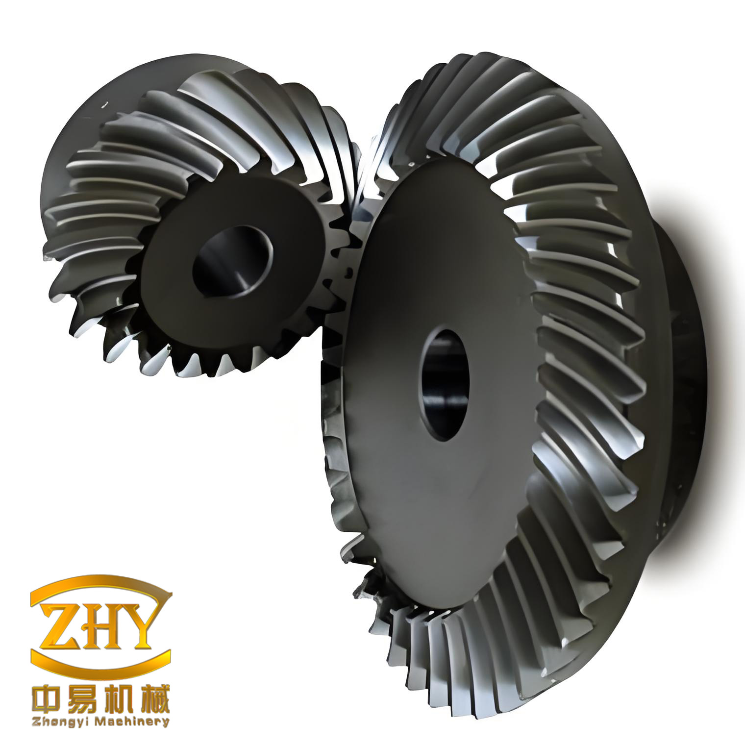
In my own work I treat the worm as a screw and the worm wheel as a partial nut. This mental model is powerful. When the worm rotates, the thread tries to advance axially. Because the worm is held in bearings, it cannot move axially. The wheel, which is free to rotate, is pushed by the thread. The direction of that push is the direction of the wheel’s tangential force. That single idea is the basis of the force method described later.
Table 1 lists the quantities I usually record first when I analyze a screw gear.
| Symbol | Quantity | Typical value or note |
|---|---|---|
| \(z_1\) | Number of starts of the worm | 1, 2, 4, or 6; small values give high reduction |
| \(z_2\) | Number of teeth on the wheel | Often 20 to 80 |
| \(m\) | Module | Standard value in mm |
| \(q\) | Diameter factor of the worm | Usually 8 to 12 |
| \(d_1\) | Pitch diameter of the worm | \(d_1 = m q\) |
| \(d_2\) | Pitch diameter of the wheel | \(d_2 = m z_2\) |
| \(a\) | Center distance | \(a = (d_1+d_2)/2\) |
| \(\gamma\) | Lead angle of the worm | \(\tan \gamma = z_1/q\) |
| \(i\) | Transmission ratio | \(i = z_2/z_1\) |
I cannot overstate the importance of the lead angle in a screw gear. It controls the efficiency, the self-locking behavior, and the force ratio. A small lead angle gives a large reduction and a strong tendency to self-lock, but it also gives low efficiency. A large lead angle gives higher efficiency but less self-locking. The direction rules, however, are independent of the numerical value of the lead angle; they depend only on the hand of the helix and the geometry of the mesh.
Essential Geometry and Formulas
Before I discuss direction, I like to write down the basic formulas of the screw gear. These formulas appear repeatedly in the examples and they help me check that I am using the correct dimensions. The pitch diameter of the worm is
$$d_1 = m q$$
and the pitch diameter of the wheel is
$$d_2 = m z_2.$$
The lead of the worm is the axial distance the thread advances in one full turn of the worm:
$$p_z = z_1 p_x = z_1 \pi m.$$
The lead angle \(\gamma\) is related to the lead and the worm pitch diameter by
$$\tan \gamma = \frac{p_z}{\pi d_1} = \frac{z_1 \pi m}{\pi d_1} = \frac{z_1 m}{d_1} = \frac{z_1}{q}.$$
The transmission ratio for a screw gear is the ratio of the worm speed to the wheel speed:
$$i = \frac{n_1}{n_2} = \frac{z_2}{z_1}.$$
The center distance is
$$a = \frac{d_1 + d_2}{2} = \frac{m(q + z_2)}{2}.$$
For force analysis I use the following relations. The tangential force on the worm is
$$F_{t1} = \frac{2T_1}{d_1}.$$
The axial force on the worm is equal to the tangential force on the wheel:
$$F_{a1} = F_{t2} = F_{t1} \cot \gamma.$$
The axial force on the wheel is equal to the tangential force on the worm:
$$F_{a2} = F_{t1}.$$
The radial force on both members is approximately
$$F_r = F_{t2} \tan \alpha_n / \cos \gamma,$$
where \(\alpha_n\) is the normal pressure angle. For many practical checks I use the simpler form
$$F_r \approx F_{t2} \tan \alpha.$$
The efficiency of a screw gear when the worm drives is
$$\eta = \frac{\tan \gamma}{\tan(\gamma + \phi_v)},$$
where \(\phi_v\) is the equivalent friction angle. When the wheel drives, the efficiency is
$$\eta’ = \frac{\tan(\gamma – \phi_v)}{\tan \gamma}.$$
If \(\eta’\) is zero or negative, the screw gear is self-locking. I will return to these formulas in the design examples, but first I need to establish the direction rules.
Step One: Determine the Hand of the Screw Gear
The hand of a screw gear is a property of the helix. It is not the same as the rotation direction. A screw can be right-hand or left-hand, and it can rotate clockwise or counterclockwise. These are independent facts. The hand is determined by the shape of the thread, while the rotation is determined by the motion input.
My preferred method for determining the hand is simple. I imagine the axis of the worm or the wheel is vertical. I look at the visible helix line. If the helix rises to the right—that is, the right side is higher than the left side—then the helix is right-hand. If the helix rises to the left—that is, the left side is higher than the right side—then the helix is left-hand. I summarize this in Table 2.
| Axis orientation | Visible helix line | Hand |
|---|---|---|
| Vertical | Right side higher, left side lower | Right-hand |
| Vertical | Left side higher, right side lower | Left-hand |
For a screw gear pair, the worm and the worm wheel must have the same hand. This is a useful check. If I determine that the worm is right-hand, then the wheel is also right-hand. If I determine that the worm is left-hand, then the wheel is also left-hand. A mismatch is impossible in a standard screw gear.
I often use a small physical model or a mental image of a standard bolt. A standard right-hand bolt, when viewed with its axis vertical, has threads that slope upward to the right. A left-hand bolt has threads that slope upward to the left. This is the same convention I use for the screw gear. The hand is a fixed property of the part, just like the direction of a thread on a bolt.
Step Two: Determine Wheel Rotation Using the Force Method
Once I know the hand, I can determine the wheel rotation by analyzing the forces at the mesh. The key fact is that the axial force on the worm \(F_{a1}\) and the tangential force on the wheel \(F_{t2}\) are equal in magnitude and opposite in direction. They form an action-reaction pair. This is the most reliable method because it follows directly from mechanics.
The procedure I use is as follows. First, I identify the hand of the screw gear. Second, I apply the correct hand rule to find the direction of the axial force on the worm. For a right-hand screw gear, I use my right hand. For a left-hand screw gear, I use my left hand. I curl my fingers in the direction of the worm’s rotation. My thumb then points in the direction of the axial force on the worm, \(F_{a1}\). Third, I reverse that direction to obtain the tangential force on the wheel, \(F_{t2}\). Fourth, I look at the contact point between the worm and the wheel. The tangential force acts on the wheel at that point. I ask: if I push the wheel at that point in that direction, which way does the wheel rotate? The answer is the wheel rotation direction.
Table 3 summarizes the hand-rule part of the procedure. The column “Fingers” refers to the direction of the worm rotation as seen along the worm axis. The column “Thumb” gives the direction of \(F_{a1}\).
| Hand of screw gear | Hand used | Fingers | Thumb gives |
|---|---|---|---|
| Right-hand | Right hand | Follow worm rotation | \(F_{a1}\) direction |
| Left-hand | Left hand | Follow worm rotation | \(F_{a1}\) direction |
I want to emphasize that the hand rule gives the axial force on the worm, not the axial force on the wheel. The axial force on the wheel is a different vector. For the wheel rotation, I need the tangential force on the wheel. Since \(F_{t2} = -F_{a1}\), I simply reverse the thumb direction. This reversal is a common source of error, so I always write it down explicitly.
Let me walk through a concrete case. Suppose the screw gear is left-hand. The worm is above the wheel in my reference view. The worm rotates downward on the side facing me. I use my left hand. I curl my fingers downward. My thumb points horizontally to the left. Therefore \(F_{a1}\) points to the left. The tangential force on the wheel is opposite, so \(F_{t2}\) points to the right. The contact point is between the worm and the wheel. If I push the wheel to the right at that contact point, the wheel rotates clockwise. So the wheel rotation is clockwise. This matches the result I get from the parity rule, which I discuss next.
Step Two Alternative: The Parity Rule
For quick checks, especially when I am standing at a machine and do not want to draw force vectors, I use a parity rule. I call it the RTUC rule. The letters stand for Right-hand, Top position, Up rotation, Clockwise wheel. The baseline case is a right-hand screw gear with the worm on top of the wheel and the worm rotating upward. In that baseline case, the wheel rotates clockwise.
The rule is a parity rule. I compare the actual situation with the baseline. I look at three binary facts: the hand, the position of the worm, and the rotation direction of the worm. If the number of differences from the baseline is even, the wheel rotates clockwise. If the number of differences is odd, the wheel rotates counterclockwise. I can write this as
$$\text{CW} \iff (H \oplus P \oplus U) = 0,$$
where \(H=0\) for right-hand and \(H=1\) for left-hand, \(P=0\) for the worm on top and \(P=1\) for the worm on the bottom, and \(U=0\) for the worm rotating upward and \(U=1\) for the worm rotating downward. The symbol \(\oplus\) denotes exclusive OR, which is the parity operation. Table 4 lists all eight combinations.
| Hand \(H\) | Position \(P\) | Worm rotation \(U\) | Parity \(H \oplus P \oplus U\) | Wheel rotation |
|---|---|---|---|---|
| Right (0) | Top (0) | Up (0) | 0 | Clockwise |
| Right (0) | Top (0) | Down (1) | 1 | Counterclockwise |
| Right (0) | Bottom (1) | Up (0) | 1 | Counterclockwise |
| Right (0) | Bottom (1) | Down (1) | 0 | Clockwise |
| Left (1) | Top (0) | Up (0) | 1 | Counterclockwise |
| Left (1) | Top (0) | Down (1) | 0 | Clockwise |
| Left (1) | Bottom (1) | Up (0) | 0 | Clockwise |
| Left (1) | Bottom (1) | Down (1) | 1 | Counterclockwise |
The parity rule is remarkably fast. I only need to remember the baseline: right-hand, worm on top, worm rotating up, wheel rotates clockwise. Then I count how many of those three conditions are reversed. An even number of reversals keeps the clockwise direction. An odd number flips it to counterclockwise. I use this rule constantly when I am checking homework or reviewing a design.
Sometimes the worm is not on top or bottom of the wheel; it may be on the left or right. In that case I mentally rotate the entire screw gear so that the worm is on top. A rotation of the whole system does not change the relative motion. I can rotate the view by \(90^\circ\) or \(270^\circ\) and then apply the parity rule. This mental rotation is easier than it sounds. I simply keep the wheel in the center and move the worm to the top position. The hand and the worm rotation direction must be rotated with the system. Once I have the canonical view, I apply Table 4.
Mathematical Derivation of the Parity Rule
The parity rule is not magic. It follows from the sign convention of the helix and the rotation. I can define a sign for each of the three binary facts. Let
$$s_H = \begin{cases} +1, & \text{right-hand} \\ -1, & \text{left-hand} \end{cases}$$
$$s_P = \begin{cases} +1, & \text{worm on top} \\ -1, & \text{worm on bottom} \end{cases}$$
$$s_U = \begin{cases} +1, & \text{worm rotates upward} \\ -1, & \text{worm rotates downward} \end{cases}$$
$$s_W = \begin{cases} +1, & \text{wheel rotates clockwise} \\ -1, & \text{wheel rotates counterclockwise} \end{cases}$$
With these definitions, the direction rule becomes
$$s_W = s_H \, s_P \, s_U.$$
This is exactly the parity statement. If an even number of the three factors are negative, the product is positive, so the wheel rotates clockwise. If an odd number are negative, the product is negative, so the wheel rotates counterclockwise. Table 5 shows the sign version of the same eight cases.
| \(s_H\) | \(s_P\) | \(s_U\) | \(s_W = s_H s_P s_U\) | Wheel rotation |
|---|---|---|---|---|
| +1 | +1 | +1 | +1 | Clockwise |
| +1 | +1 | -1 | -1 | Counterclockwise |
| +1 | -1 | +1 | -1 | Counterclockwise |
| +1 | -1 | -1 | +1 | Clockwise |
| -1 | +1 | +1 | -1 | Counterclockwise |
| -1 | +1 | -1 | +1 | Clockwise |
| -1 | -1 | +1 | +1 | Clockwise |
| -1 | -1 | -1 | -1 | Counterclockwise |
This derivation also shows that if I flip any two of the three conditions, the wheel direction does not change. That is why an even number of flips preserves the clockwise direction. It also shows that I can solve for any unknown sign if I know the other three. For example, if I know the hand, the position, and the wheel direction, I can find the worm rotation by
$$s_U = \frac{s_W}{s_H s_P}.$$
This is a compact and powerful way to think about the problem.
Comparing the Force Method and the Parity Rule
Both methods give the same answer. I have tested them on many examples, and I have never found a contradiction. The force method is more fundamental because it explains why the wheel rotates. The parity rule is faster because it reduces the problem to counting. Table 6 compares the two methods from my perspective.
| Feature | Force method | Parity rule |
|---|---|---|
| Basis | Action-reaction and hand rule | Parity of three binary facts |
| Speed | Moderate; requires drawing vectors | Very fast; requires counting flips |
| Accuracy | Excellent; directly from mechanics | Excellent if baseline is remembered |
| Best use | Verification, teaching, complex cases | Quick checks, field work, exams |
| Prerequisites | Hand rule, force directions | Baseline case, parity counting |
| Common error | Forgetting to reverse \(F_{a1}\) to get \(F_{t2}\) | Using the wrong hand or wrong position |
My personal workflow is to use the parity rule first. If the answer is not obvious, or if the geometry is unusual, I confirm with the force method. The two methods together make the direction of a screw gear almost impossible to get wrong.
Common Mistakes and How I Avoid Them
Over the years I have seen many mistakes in determining the direction of a screw gear. Most of them come from confusing the different attributes of the system. Table 7 lists the mistakes I see most often, the symptoms, and the correction I use.
| Mistake | Symptom | Correction |
|---|---|---|
| Confusing hand with rotation | Thinking that a right-hand worm must rotate clockwise | Remember that hand is a property of the helix; rotation is independent |
| Using the wrong hand | Applying the right-hand rule to a left-hand screw gear | Use the right hand for right-hand, left hand for left-hand |
| Forgetting the reversal | Using \(F_{a1}\) directly as the force on the wheel | Remember \(F_{t2} = -F_{a1}\) |
| Ignoring worm position | Applying the parity rule without noting whether the worm is top or bottom | Always identify \(P\) before counting parity |
| Inconsistent viewing direction | Mixing clockwise and counterclockwise from different views | Choose a reference view and rotate the whole system mentally |
| Mismatching hands | Assuming the wheel has a different hand from the worm | In a standard screw gear, worm and wheel have the same hand |
I have also seen students try to memorize every possible combination. That is unnecessary. The parity rule reduces the eight combinations to one baseline plus a count. The force method reduces the problem to one hand rule plus one reversal. Both are much easier to remember than a long list.
Applications of Screw Gear in Industry
I have encountered screw gear pairs in many different machines. The direction of rotation is often critical because it determines the motion of a load, the direction of a conveyor, or the engagement of a safety device. Table 8 lists some common applications and the typical direction requirements I have seen.
| Industry | Typical use of screw gear | Typical ratio | Direction requirement |
|---|---|---|---|
| Machine tools | Indexing tables, feed drives | 20:1 to 100:1 | Precise and repeatable |
| Automotive | Window lifts, seat adjusters | 30:1 to 200:1 | Often self-locking |
| Instruments | Fine positioning, tuning mechanisms | 50:1 to 300:1 | Low backlash |
| Cranes and hoists | Load lifting and holding | 40:1 to 200:1 | Self-locking for safety |
| Metallurgical machinery | Roll adjustment, conveyors | 10:1 to 80:1 | High torque, robust |
| Packaging | Timing and indexing | 20:1 to 120:1 | Fast response |
In every one of these applications, I need to know which way the wheel turns before I can specify the bearing arrangement, the lubrication, and the control system. The parity rule and the force method are therefore not academic exercises; they are practical design tools.
Materials and Manufacturing Considerations
The materials of a screw gear depend on the load, the speed, and the environment. I usually pair a hardened steel worm with a bronze wheel. The steel worm resists wear, and the bronze wheel provides good sliding properties and embeddability. Table 9 lists some material combinations I have used.
| Worm material | Wheel material | Hardness | Typical application |
|---|---|---|---|
| Case-hardened alloy steel | Tin bronze | 58–62 HRC | High-speed, high-load screw gear |
| Through-hardened carbon steel | Phosphor bronze | 45–55 HRC | Medium-duty screw gear |
| Nitrided steel | Aluminum bronze | 60–65 HRC | Heavy-duty, slow-speed screw gear |
| Stainless steel | Bronze | 30–40 HRC | Corrosive environments |
| Plastic worm | Plastic wheel | — | Light-duty, quiet screw gear |
The manufacturing of a screw gear requires accurate helix generation. The hand must be cut correctly. A right-hand worm cannot be paired with a left-hand wheel. I always verify the hand before assembly. If the hand is wrong, the screw gear will not mesh properly, and the direction will be wrong even if the rotation rule is applied correctly.
Lubrication and Cooling
Lubrication is especially important in a screw gear because the motion involves significant sliding. The efficiency and the temperature rise depend on the lubricant. I use the following formulas to estimate the power loss and the temperature rise.
$$P_{\text{loss}} = P_1 (1 – \eta).$$
$$\Delta T = \frac{P_{\text{loss}}}{K A}.$$
Here \(P_1\) is the input power, \(\eta\) is the efficiency, \(K\) is the heat transfer coefficient, and \(A\) is the effective cooling area. Table 10 lists typical lubricant choices for different sliding speeds.
| Sliding speed | Lubricant type | Viscosity grade | Cooling method |
|---|---|---|---|
| Low | Grease | NLGI 2 | Natural convection |
| Medium | Mineral oil | ISO VG 220 | Splash lubrication |
| High | Synthetic oil | ISO VG 320 | Forced circulation |
| Very high | Synthetic oil with cooling | ISO VG 460 | Oil cooler |
The direction of rotation can affect the oil flow. In a horizontal screw gear, the worm may be above or below the wheel. If the worm is above, the oil is carried by the wheel and splashed onto the worm. If the worm is below, the worm dips into the oil. The parity rule tells me the wheel direction, which in turn tells me which side of the housing receives the most oil. I use this information to position the oil level and the drain plug.
Assembly and Alignment
When I assemble a screw gear, I follow a sequence that minimizes the chance of a direction error. Table 11 lists the steps I use.
| Step | Action | Check |
|---|---|---|
| 1 | Identify the hand of the worm and wheel | Both must be the same |
| 2 | Mount the worm in its bearings | Axial play within specification |
| 3 | Mount the wheel on its shaft | Runout within tolerance |
| 4 | Bring the axes to the correct center distance | \(a = (d_1+d_2)/2\) |
| 5 | Check the contact pattern | Contact centered on the tooth |
| 6 | Rotate the worm by hand | Wheel turns in the predicted direction |
| 7 | Apply load and check temperature | \(\Delta T\) within limits |
Step 6 is the moment of truth. I always predict the wheel direction before I turn the worm. If the prediction is wrong, I stop and recheck the hand and the position. In my experience, a wrong prediction almost always means that I misidentified the hand or that I used the wrong reference view.
Troubleshooting Direction Problems
Even with a good method, problems can occur. Table 12 lists the symptoms I have seen and the solutions I use.
| Symptom | Likely cause | Solution |
|---|---|---|
| Wheel turns opposite to prediction | Hand misidentified | Recheck the helix with the axis vertical |
| Wheel turns opposite to prediction | Worm position misread | Redraw the view with the worm on top |
| Wheel turns opposite to prediction | Hand rule applied with the wrong hand | Use right hand for right-hand, left hand for left-hand |
| Wheel does not turn smoothly | Wrong hand on wheel | Replace the wheel with the matching hand |
| Excessive noise | Incorrect lead angle or backlash | Check the lead angle and the center distance |
| Overheating | Low efficiency or poor lubrication | Increase the lead angle or improve cooling |
I have found that most direction problems are caused by a simple misreading of the hand or the position. The parity rule is so quick that I can test several possibilities in my head before I commit to an answer.
Worked Design Examples
In this section I present several worked examples that I use in my own notes. Each example includes the geometry, the direction question, and the solution using both methods where practical. I have chosen numbers that are easy to follow, but the logic applies to any screw gear.
Example A: Basic Geometry and Direction
Consider a screw gear with \(z_1 = 2\), \(z_2 = 40\), \(m = 4\) mm, and \(q = 10\). I first compute the basic dimensions.
$$d_1 = m q = 4 \times 10 = 40 \text{ mm}.$$
$$d_2 = m z_2 = 4 \times 40 = 160 \text{ mm}.$$
$$a = \frac{d_1 + d_2}{2} = \frac{40 + 160}{2} = 100 \text{ mm}.$$
$$\tan \gamma = \frac{z_1}{q} = \frac{2}{10} = 0.2.$$
$$\gamma = \arctan(0.2) \approx 11.31^\circ.$$
$$i = \frac{z_2}{z_1} = \frac{40}{2} = 20.$$
Now suppose the worm is right-hand, the worm is on top of the wheel, and the worm rotates upward. Using the parity rule, the situation is exactly the baseline, so the wheel rotates clockwise. Using the force method, I use my right hand, curl my fingers upward, and my thumb points in the direction of \(F_{a1}\). The tangential force on the wheel is opposite, and the resulting wheel rotation is clockwise. The two methods agree.
If the friction angle is \(\phi_v = 3^\circ\), the efficiency when the worm drives is
$$\eta = \frac{\tan \gamma}{\tan(\gamma + \phi_v)} = \frac{\tan(11.31^\circ)}{\tan(14.31^\circ)} \approx \frac{0.2}{0.255} \approx 0.784.$$
So the screw gear is about \(78.4\%\) efficient. The self-locking condition is \(\gamma \le \phi_v\). Here \(11.31^\circ > 3^\circ\), so the screw gear is not self-locking. This is an important design check.
Example B: Left-Hand, Bottom Position, Downward Rotation
Now consider a screw gear that is left-hand. The worm is on the bottom of the wheel, and it rotates downward in my reference view. I want the wheel rotation. Using the parity rule, I compare with the baseline: right-hand (0), top (0), up (0). The actual situation is left-hand (1), bottom (1), down (1). The number of flips is three, which is odd. Therefore the wheel rotates counterclockwise. Table 4 confirms this result.
Using the force method, I use my left hand because the screw gear is left-hand. I curl my fingers downward. My thumb points in the direction of \(F_{a1}\). I reverse that to get \(F_{t2}\). The contact point is at the bottom of the wheel. The tangential force pushes the wheel in the direction that produces counterclockwise rotation. Again the methods agree.
Example C: Finding the Worm Rotation from the Wheel Rotation
Sometimes I know the wheel rotation and I need the worm rotation. For example, suppose the screw gear is right-hand, the worm is on top, and the wheel rotates clockwise. What is the worm rotation? I set \(H=0\), \(P=0\), and I want the wheel clockwise, so the parity must be even. Therefore \(U\) must be 0. So the worm rotates upward. This is the baseline case. If the wheel rotates counterclockwise instead, the parity must be odd, so \(U=1\), and the worm rotates downward.
Example D: Left-Hand, Top Position, Counterclockwise Wheel
Suppose the screw gear is left-hand, the worm is on top, and the wheel rotates counterclockwise. I need the worm rotation. I have \(H=1\), \(P=0\). The wheel is counterclockwise, so the parity must be odd. Therefore \(1 + 0 + U \equiv 1 \pmod 2\), which gives \(U \equiv 0 \pmod 2\). So \(U=0\), and the worm rotates upward. Checking Table 4, the row for left-hand, top, up gives counterclockwise. The answer is consistent.
Example E: Left-Hand, Bottom Position, Clockwise Wheel
Now suppose the screw gear is left-hand, the worm is on the bottom, and the wheel rotates clockwise. I need the worm rotation. I have \(H=1\), \(P=1\). The wheel is clockwise, so the parity must be even. Therefore \(1 + 1 + U \equiv 0 \pmod 2\), which gives \(U \equiv 0 \pmod 2\). So \(U=0\), and the worm rotates upward. Table 4 confirms that left-hand, bottom, up gives clockwise. The answer is upward rotation.
These examples show that the parity rule is not just a mnemonic; it is a complete algebraic method. I can solve for any one unknown if I know the other three facts.
Example F: Full Force Analysis with Numbers
Let me now work through a complete force analysis for a screw gear. Suppose the input torque on the worm is \(T_1 = 50 \text{ N·m}\). The worm has \(d_1 = 40 \text{ mm} = 0.04 \text{ m}\). The lead angle is \(\gamma = 11.31^\circ\). I compute the tangential force on the worm:
$$F_{t1} = \frac{2T_1}{d_1} = \frac{2 \times 50}{0.04} = 2500 \text{ N}.$$
The axial force on the worm is
$$F_{a1} = F_{t1} \cot \gamma = 2500 \times \cot(11.31^\circ) \approx 2500 \times 5.0 = 12500 \text{ N}.$$
This is also the tangential force on the wheel, \(F_{t2} = 12500 \text{ N}\). The axial force on the wheel is
$$F_{a2} = F_{t1} = 2500 \text{ N}.$$
The radial force, assuming \(\alpha = 20^\circ\), is approximately
$$F_r \approx F_{t2} \tan \alpha = 12500 \times 0.364 = 4550 \text{ N}.$$
These forces are used to select the bearings and the shaft diameters. The direction of the forces depends on the hand and the rotation direction. If the screw gear is right-hand and the worm rotates upward, then \(F_{a1}\) points in one axial direction. If the worm rotates downward, \(F_{a1}\) reverses. I always note the direction on the drawing so that the bearing arrangement can be designed correctly.
Force Directions and Vector Formulation
For readers who prefer vectors, I can express the direction logic in a more formal way. Let the worm axis be the \(x\)-axis and the wheel axis be the \(z\)-axis. The contact point lies on the \(y\)-axis at some distance \(r\) from the wheel axis. The worm axial force \(F_{a1}\) is along the \(x\)-axis. The wheel tangential force \(F_{t2}\) is also along the \(x\)-axis because the wheel rotates about the \(z\)-axis. The relationship is
$$\vec{F}_{t2} = -\vec{F}_{a1}.$$
The wheel angular velocity vector is \(\vec{\omega}_2 = \omega_2 \hat{z}\). The velocity of the contact point on the wheel is
$$\vec{v}_2 = \vec{\omega}_2 \times \vec{r} = \omega_2 \hat{z} \times r \hat{y} = -\omega_2 r \hat{x}.$$
Therefore the direction of \(\vec{v}_2\) is opposite to the direction of \(\vec{F}_{t2}\) if \(\omega_2\) is positive. The sign of \(\omega_2\) determines whether the wheel rotates clockwise or counterclockwise in the chosen view. This vector approach is elegant, but in practice I find the hand rule and the parity rule faster.
For the forces, the full set of relations for a screw gear is
$$F_{t1} = \frac{2T_1}{d_1},$$
$$F_{a1} = F_{t2} = F_{t1} \cot \gamma,$$
$$F_{a2} = F_{t1},$$
$$F_r = F_{t2} \tan \alpha_n / \cos \gamma.$$
These equations are useful for bearing selection and shaft design. The direction rules tell me the signs of the forces; the equations tell me the magnitudes. I always use both.
Screw Gear Performance and Design Notes
Direction is only one part of screw gear design. A complete design also considers efficiency, heat, lubrication, and self-locking. I include this section because the direction of rotation can affect the lubrication and the wear pattern. For example, in a self-locking screw gear, the worm can drive the wheel but the wheel cannot drive the worm. This is often used in hoists and lifting devices. The direction of the helix and the lead angle both play a role.
Table 13 lists typical efficiency values for a screw gear as a function of the lead angle. The values are approximate and depend on lubrication and materials.
| Lead angle \(\gamma\) | Typical efficiency \(\eta\) | Self-locking tendency |
|---|---|---|
| \(< 5^\circ\) | 0.30 – 0.50 | Strong |
| \(5^\circ – 10^\circ\) | 0.50 – 0.70 | Moderate |
| \(10^\circ – 20^\circ\) | 0.70 – 0.85 | Weak |
| \(20^\circ – 30^\circ\) | 0.85 – 0.92 | Very weak |
| \(> 30^\circ\) | 0.92 – 0.96 | None |
The power loss in a screw gear is
$$P_{\text{loss}} = P_1 (1 – \eta).$$
The temperature rise of the lubricant can be estimated from
$$\Delta T = \frac{P_{\text{loss}}}{K A},$$
where \(K\) is the heat transfer coefficient and \(A\) is the effective cooling area. If the temperature rise is too high, I increase the cooling area or reduce the power. The direction of rotation does not change these equations, but it can change the oil flow pattern in the housing.
For self-locking, I use the condition
$$\eta’ = \frac{\tan(\gamma – \phi_v)}{\tan \gamma} \le 0.$$
This occurs when \(\gamma \le \phi_v\). For a screw gear with \(\gamma = 5^\circ\) and \(\phi_v = 6^\circ\), the reverse efficiency is negative, so the screw gear is self-locking. Such a pair is safe for holding loads without a brake, but it has low forward efficiency. I always check this condition before I specify a screw gear for a lifting application.
A Personal Checklist for Screw Gear Direction
I have reduced my entire procedure to a checklist. I use it whenever I need to determine the direction of a screw gear. Table 14 presents the checklist in the order I follow.
| Step | Action | Formula or rule | Output |
|---|---|---|---|
| 1 | Identify the helix hand | Axis vertical; right high = right-hand, left high = left-hand | Right or left |
| 2 | Confirm worm and wheel have the same hand | Standard screw gear property | Consistent hand |
| 3 | Choose a reference view | Worm on top or bottom; observe rotation | \(H, P, U\) |
| 4 | Apply parity rule | Even flips = clockwise; odd flips = counterclockwise | Wheel rotation |
| 5 | Verify with force method | Use correct hand; \(F_{t2} = -F_{a1}\) | Confirmation |
| 6 | Check design consequences | Efficiency, self-locking, heat | Design decision |
I keep this checklist in my notebook. It takes less than a minute to run through, and it eliminates almost all direction errors. When I teach this material, I ask students to use the checklist until they can apply the parity rule mentally.
Summary of Rules
Table 15 summarizes the rules I use for screw gear direction. I have written them in a compact form so that they can be memorized easily.
| Rule | Statement |
|---|---|
| Hand rule | Right-hand screw gear uses right hand; left-hand uses left hand. Fingers follow worm rotation; thumb gives \(F_{a1}\). |
| Action-reaction | \(F_{t2} = -F_{a1}\). Reverse the thumb direction to get the wheel tangential force. |
| Parity baseline | Right-hand, top, up \(\Rightarrow\) clockwise. |
| Parity count | Even number of flips from baseline \(\Rightarrow\) clockwise; odd number \(\Rightarrow\) counterclockwise. |
| View rotation | If the worm is not top or bottom, mentally rotate the entire screw gear to the canonical view. |
| Hand consistency | Worm and wheel have the same hand in a standard screw gear. |
Frequently Asked Questions
Question: Can I use the parity rule if the worm is on the left or right of the wheel?
Answer: Yes. I mentally rotate the entire screw gear so that the worm is on top. The relative motion does not change under a rigid rotation. I then apply the parity rule in the canonical view.
Question: What if I do not know the hand of the screw gear?
Answer: I place the axis vertical and look at the helix. If the visible line rises to the right, it is right-hand. If it rises to the left, it is left-hand. I can also check the wheel; it must have the same hand as the worm.
Question: Does the lead angle affect the direction?
Answer: No. The lead angle affects the efficiency, the self-locking, and the force magnitudes, but it does not change the direction of rotation. Direction depends only on the hand, the position, and the rotation of the worm.
Question: Why do I need to reverse the thumb direction in the force method?
Answer: The thumb gives the axial force on the worm, \(F_{a1}\). The force that turns the wheel is the tangential force on the wheel, \(F_{t2}\). These two forces are equal and opposite, so I must reverse the direction.
Question: Can a screw gear be self-locking in both directions?
Answer: Self-locking means that the wheel cannot drive the worm. It is a property of the lead angle and the friction angle. If \(\gamma \le \phi_v\), the screw gear is self-locking when the wheel tries to drive. The forward drive is still possible, but the efficiency is low.
Final Thoughts
I have used the methods in this article for many years, and they have never failed me. The force method explains the physics, while the parity rule provides speed. Together they make the direction of a screw gear a routine calculation rather than a source of uncertainty. I encourage anyone who works with screw gear systems to adopt a consistent convention, practice the parity rule, and verify with the force method when the geometry is unusual. Once the convention is fixed, the answer is always the same, and the screw gear becomes as predictable as any other transmission.
In my own design work I now spend less time worrying about which way the wheel turns and more time optimizing the lead angle, the materials, and the lubrication. That is the real benefit of mastering the direction rules. The screw gear is a compact, quiet, and high-ratio transmission, and with a reliable direction method it is also a pleasure to design.