
Kinematic model of strong tooth scraping take spur gear as an example. The kinematic model of strong tooth scraping is shown in the figure.
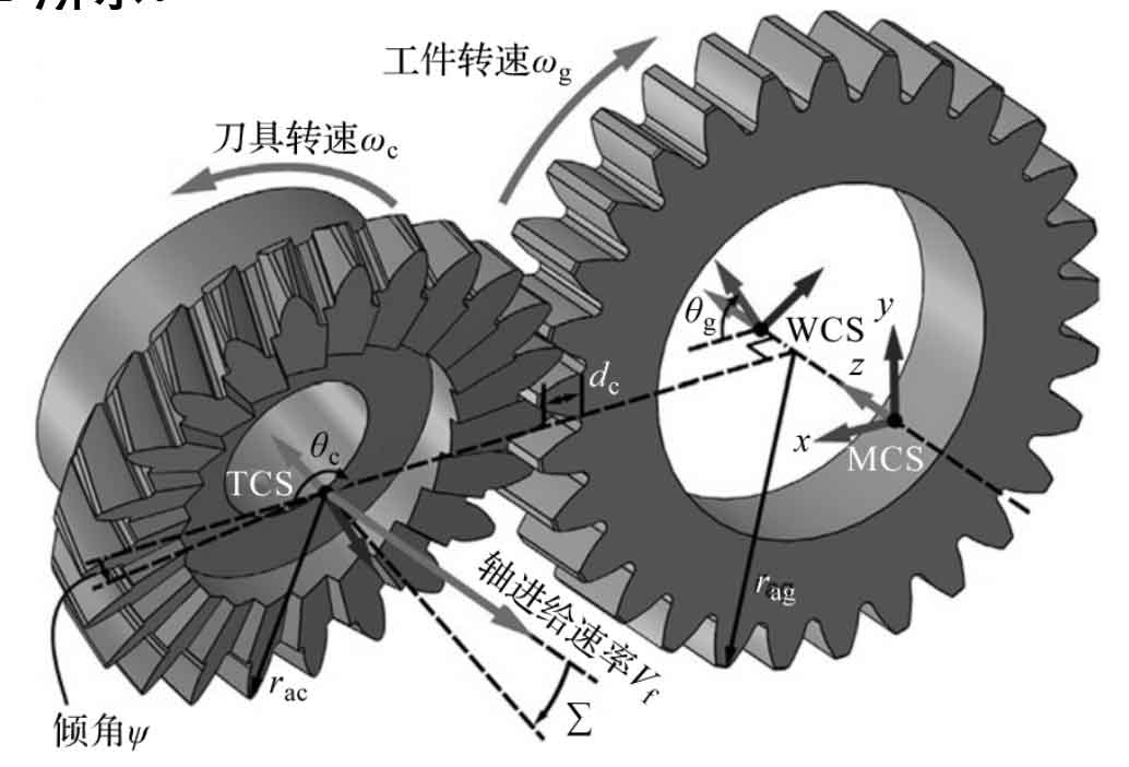
As shown in the figure, the tool is oriented at a cross axis angle Σ around the X axis of the machine coordinate system (MCS). When the tool is fed along the Z axis of the workpiece at a constant speed VF, the cutting motion is completed by relative rotation between the tool and the workpiece; In each machining process, the tool is positioned radially into the workpiece at the specified depth DC. Inclination defined around the Y-axis of the MCS ψ It can also be applied to tools for tooth profile trimming or to provide additional clearance. Because the rotation speed of the tool is based on the cylindrical gear ratio of the tool workpiece, which is a function of the number of cylindrical gear teeth and the number of tool teeth.
For helical gears with similar motion, the required helix angle will produce additional rotation items according to the pitch radius and axial feed speed of the tool, namely:
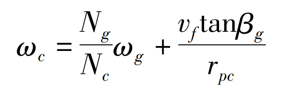
Where: ω C – tool speed; ω G – rotating speed of workpiece; Ng – number of gear teeth; NC – number of tool teeth; β G – gear helix angle; RPC – tool pitch radius; VF – the feed rate of the tool along the Z axis of the workpiece.
In order to be compatible with the dexel model required for tool workpiece meshing calculation, it is necessary to establish the kinematic model of strong tooth scraping in the workpiece coordinate system (WCS). Since the tool geometry is defined in the tool coordinate system (TCS), the product of homogeneous transformation is applied here, including a single rotation R and translation T, as shown below:
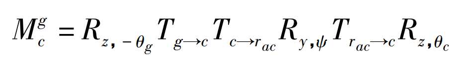
Where: RZ, - θ G – the gear rotates reversely about its z-axis θ g ; Rz, θ C – the gear rotates about its z-axis θ c; TG → C – Translation from workpiece to tool in MCS; Tc→racRy, ψ Trac → C – tool angle ψ Tilt of the.
In industrial practice, the cutting speed is usually defined as VC ω crpc。 However, the size and direction of the actual cutting speed will show obvious changes on the blade, resulting in the continuous change of the contact conditions of local inclination. Therefore, it is necessary to accurately solve the cutting speed vector. For a given point P on the scraper, whose positions are RP / C (relative to the tool) and RP / g (relative to the workpiece), the real cutting speed can be found in WCS or TCS using the speed vector, i.e.:
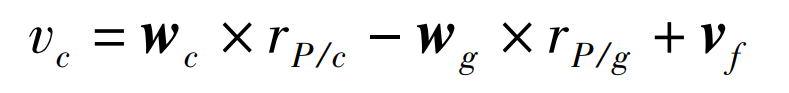
Where: WC – tool speed vector; WG – rotational speed vector of workpiece; VF – speed vector of the tool feeding along the Z axis of the workpiece.