
Gleason’s idea of designing hypoid gear pair is to calculate the contact parameters of hypoid gear pair. When studying the helix angle, pressure angle and motion parameters of hypoid gear pair, we should first study the conjugate motion relationship at the node. The coordinate system is established with the pitch plane of hypoid gear pair as the reference plane δ e. Take the three unit vectors E1, E2 and E3 as δ The three axes of E, as shown in Figure 1, E1 is along the tangent direction of the tooth line in the pitch plane of the hypoid gear pair, E3 is perpendicular to the pitch plane and along the direction of k2k1, and E2 is in the pitch plane, which can be determined by the right-hand rule, E1, E2 and E3.
As shown in Figure 1, the big gear rotates right and the pinion rotates left. In the figure, β 1 is the included angle between the pinion pitch cone bus and the tooth line tangent vector E1, which is called the pinion helix angle; β 2 should be the included angle between the large pitch cone bus and the tangential E1 of the tooth line, which is called the helical angle of the large gear. From the figure, β 1、 β 2 offset angle with hypoid gear ε’ That is, the relationship between the included angle of the two gear section cone buses:
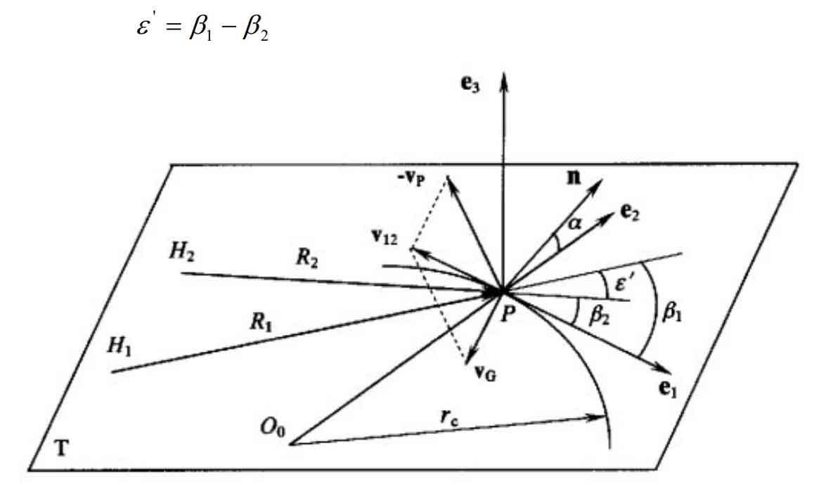
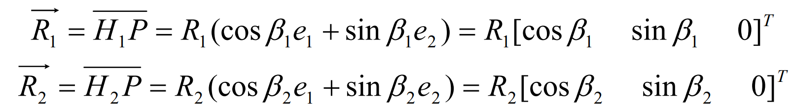
When coordinate system δ E, the vectors R1 and R2 at node P can be expressed as,
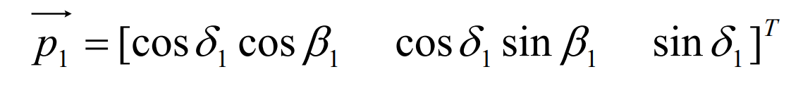
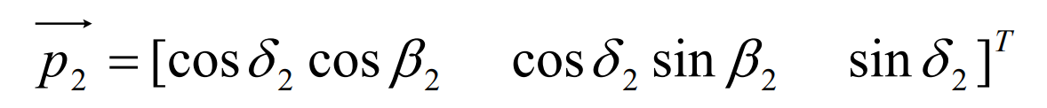
Let P2 and P1 be the unit vectors in the directions of the big and small gear axes h1k1 and h2k2 respectively, and the included angles between them and the pitch plane of the gear pair are respectively δ 2 、 δ 1. Available,
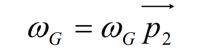
Set the number of teeth of large and small gears as Z2 and Z1 respectively, and take the large gear as the first tooth surface, then the angular speed of the large gear is,
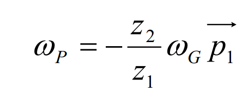
Similarly, the angular velocity of hypoid gear pinion is:
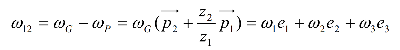
According to the above formula, the relative angular velocity of hypoid gear is:
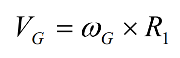
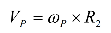
The speed of the tooth surface of hypoid gear and large gear at node P,
The speed of the tooth surface of hypoid gear pinion at node P,
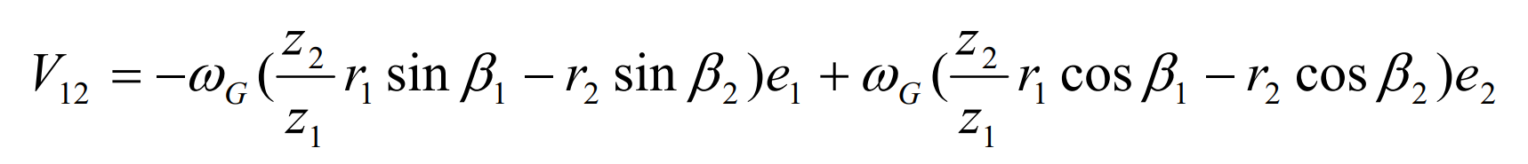
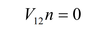
Then the relative motion speed of hypoid gear at node P V12 = VG – VP can be expressed as:
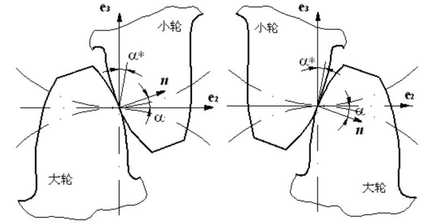
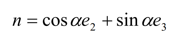
Let n be the common normal vector of the big gear and the small gear at node P, then the included angle between N and the pitch plane is called the pressure angle of the hypoid gear. As shown in Figure 2 (1), the figure is the conjugate state when the convex surface of the big gear and the concave surface of the small gear mesh, in which the common normal vector n is written as:
For the conjugate state of the concave surface of the big gear and the convex surface of the small gear in Fig. 2 (2), n can be expressed as:
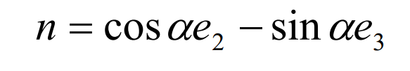
In order to facilitate the expression, the pressure angle when the concave surface of the big gear is conjugate with the convex surface of the small gear is set as a negative value, so that the pressure angle can be expressed in the first formula under different conditions.
According to the meshing principle, the conjugate surface must meet the meshing equation at the meshing point:
From the above formula:
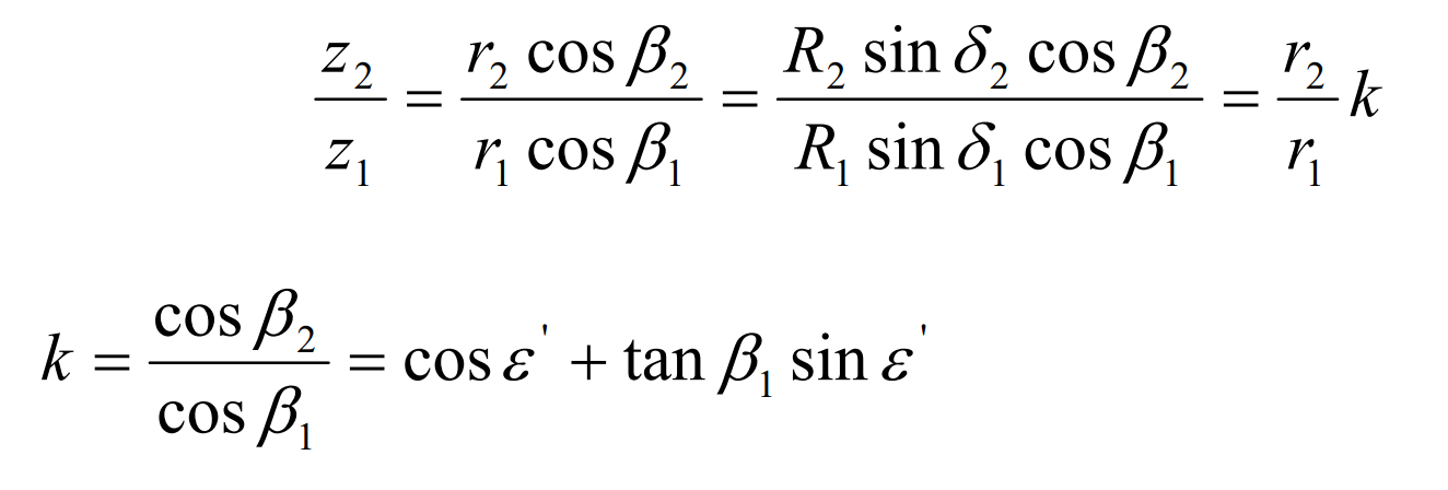
In the formula, the parameter k is called the amplification factor of hypoid gear transmission. Then the relative angular velocity component and relative velocity of hypoid gear at node P are respectively:
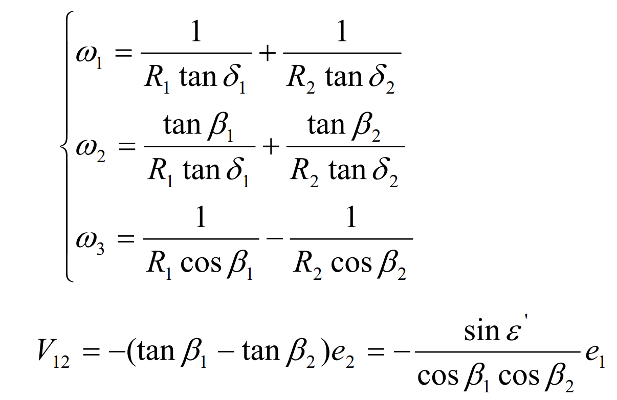
According to the above formula, in theory, the relative motion speed of the hypoid gear pair in the meshing process is only a component along the E1 direction, which shows that the hypoid gear pair has relative motion only in the tooth line direction and no relative sliding in the meshing transmission process.