
As ocean engineering equipment continues to advance toward deeper and farther offshore operations, the demand for reliable and highly load-capable jack-up platform lifting systems has increased substantially. In my research, I focus on the large-modulus heavy-load 7-tooth rack and pinion gear transmission system, which is widely used because of its high transmission efficiency, simple structure, smooth operation, strong load-bearing capacity, and compact space occupation. The central challenge is that current design standards do not fully cover the calculation of load capacity for 7-tooth rack and pinion gear systems with a modulus greater than 50. Therefore, I combined orthogonal experimental design with finite element transient dynamic analysis to propose a systematic design and optimization method for large-modulus heavy-load 7-tooth rack and pinion gear pairs.
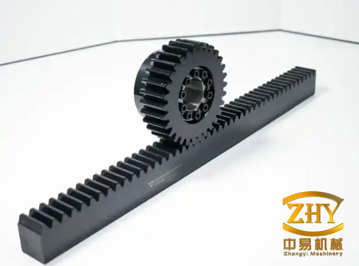
In my study, the modulus, pressure angle, and modification coefficient of the large-modulus heavy-load 7-tooth rack and pinion gear are treated as design variables. The objective is to minimize the root stresses on both the tensile and compressive sides of the gear tooth. I used HyperMesh and ANSYS for finite element transient dynamic simulation. The contact algorithm between the contact surface elements (CONTACT174) and target surface elements (TARGE170) was combined with the MPC184 rotation pair algorithm to build a simplified model. This approach allows me to capture the stress variation during the entire meshing process of the rack and pinion gear.
My analysis shows that the tooth profile design of a large-modulus heavy-load 7-tooth rack and pinion gear must satisfy several practical constraints. First, the tooth tip must not be too thin because the carburizing and quenching process can cause through-hardening, leading to brittle fracture under heavy load. Second, the 7-tooth gear must not be undercut. Third, the longest possible tooth profile and the largest possible root transition radius should be used to reduce stress concentration and improve load capacity. Based on these principles, I derived the non-undercutting condition for the rack and pinion gear as follows:
$$ x_1 = \frac{1}{2} m z_1 + h_a^* m – \frac{1}{2} m z_1 \cos^2 \alpha \geq h_a^* m – x m $$
where \(x_1\) is the rack tip clearance, \(m\) is the modulus, \(z_1\) is the number of teeth, \(h_a^*\) is the addendum coefficient, \(\alpha\) is the pressure angle, and \(x\) is the modification coefficient. For a 7-tooth rack and pinion gear, this condition is critical because the number of teeth is far below the standard undercut limit of 14 teeth for a 20° pressure angle.
I also analyzed the influence of the main parameters on the load capacity of the rack and pinion gear. The modulus directly affects the tooth thickness and bending strength. A larger modulus increases the tooth root thickness, but it also increases the radial size and reduces the number of teeth in contact. The pressure angle affects both the root thickness and the curvature radius of the involute profile. A larger pressure angle generally increases the root strength but reduces the contact ratio. The modification coefficient can effectively increase the root thickness and avoid undercutting, but excessive positive modification can make the rack tooth tip too sharp and reduce the contact ratio. The contact ratio of a large-modulus heavy-load 7-tooth rack and pinion gear is inherently low, so I must carefully balance these factors.
For the load capacity calculation, I reviewed the standard methods, including the flat-section method, the folded-section method, the elastic mechanics method, and the finite element method. The flat-section method, which is the basis of many national and international standards, assumes that the maximum tensile stress at the root is the critical stress. However, for a large-modulus heavy-load 7-tooth rack and pinion gear, my simulation results show that the compressive stress on the root is often significantly higher than the tensile stress. Moreover, the standard formulas include empirical correction factors that are not validated for modulus values above 50. Therefore, the standard calculation method is not suitable for this type of rack and pinion gear. Instead, I adopted the finite element method to obtain the stress distribution and the stress history during meshing.
To estimate the initial modulus for a given load, I used a simplified formula derived from finite element results. The nominal tooth root stress can be expressed as:
$$ \sigma_{F0} = K \frac{F_t}{b m} $$
where \(F_t\) is the tangential force, \(b\) is the face width, \(m\) is the modulus, and \(K\) is a composite coefficient that depends on the tooth number, modification coefficient, root fillet radius, and the position of the highest point of single tooth contact. Based on this relationship, the required modulus for a given load can be estimated by:
$$ m \geq \left( \frac{K F_t}{b \sigma_{FP}} \right)^{1/2} $$
where \(\sigma_{FP}\) is the allowable root stress. Using this approach, I obtained the initial modulus values for five load levels, as shown in Table 1. These values were then rounded and used in the orthogonal experiment.
| Load (ton) | Estimated modulus (mm) | Rounded modulus for orthogonal design (mm) |
|---|---|---|
| 100 | 49.834 | 49, 50, 51 |
| 125 | 55.716 | 55, 56, 57 |
| 160 | 63.036 | 62, 63, 64 |
| 200 | 70.476 | 70, 71, 72 |
| 250 | 78.794 | 78, 79, 80 |
For the finite element modeling, I used AutoCAD to generate the involute profile and the rack profile, and SolidWorks to create the 3D solid models. The models were then imported into HyperMesh for meshing. I used hexahedral elements (Solid186) with a mapped mesh algorithm. The mesh density was controlled to keep the number of elements between 100,000 and 150,000, and the node count between 100,000 and 150,000. The mesh quality was checked to ensure no free edges or T-shaped edges, and the minimum quality was above 0.8. The material properties for the gear and rack are listed in Table 2. The gear material is 40CrNiMo (AISI4340) and the rack material is Q690. The gear is carburized and quenched, while the rack is used as-welded with a yield strength of at least 690 MPa.
| Property | Gear | Rack |
|---|---|---|
| Material | 40CrNiMo (AISI4340) | Q690 |
| Density (kg/m³) | 7850 | 7850 |
| Elastic modulus (GPa) | 210 | 210 |
| Poisson’s ratio | 0.3 | 0.3 |
| Friction coefficient | 0.15 | 0.15 |
| Yield strength (MPa) | 1040 | 690 |
| Tensile strength (MPa) | 1200 | 850 |
| Contact fatigue limit (MPa) | 1500 | 900 |
| Bending fatigue limit (MPa) | 529 | 381 |
The boundary conditions were applied using the MPC184 element for the gear rotation. A beam element (BEAM188) was used to define the gear bore, and the MPC184 element was connected to the inner cylindrical surface of the gear. By constraining the beam element and applying a rotational displacement to the MPC184 element, the gear was forced to rotate about its axis. For the rack, the Y and Z translational degrees of freedom were constrained on the non-tooth region, and a distributed force was applied to the rack face to resist the gear rotation. The contact pair was defined with CONTACT174 on the gear surface and TARGE170 on the rack surface. The normal penalty stiffness was set to 0.1, and the friction coefficient was 0.15. The augmented Lagrangian algorithm was used to solve the nonlinear contact problem.
I used the APDL command stream to apply the displacement and force loads. The gear was rotated at a speed of 0.351 r/min, which corresponds to an angular velocity of \(3.6757 \times 10^{-2}\) rad/s. The load was applied as a ramp function over 25 seconds. The first load step from 0 to 1 second ensured that contact was established. The second load step from 1 to 25 seconds applied the full load and refined the substeps to improve accuracy. The large deformation effect and time integration were activated. The solution was obtained using the transient dynamic module with the HHT time integration method.
For the orthogonal experiment, I selected three factors: modulus, pressure angle, and modification coefficient. The modulus had three levels, while the pressure angle and modification coefficient each had four levels. A full factorial design would require \(3 \times 4 \times 4 = 48\) simulations, which is computationally expensive. Therefore, I used an orthogonal array to reduce the number of simulations to 16. The factors and levels are shown in Table 3. The pressure angle levels were 26°, 27°, 28°, and 29°, and the modification coefficient levels were 0.05, 0.1, 0.15, and 0.2. The modulus levels were chosen based on the load level, as shown in Table 1.
| Level | Modulus (mm) | Pressure angle (°) | Modification coefficient |
|---|---|---|---|
| 1 | Low | 26 | 0.05 |
| 2 | Medium | 27 | 0.10 |
| 3 | High | 28 | 0.15 |
| 4 | — | 29 | 0.20 |
After running the 16 simulations for each load level, I obtained the maximum root stresses on the tensile and compressive sides of the gear tooth. The results for the 100-ton load are shown in Table 4 as an example. The complete set of results for all five load levels is summarized in the range analysis and variance analysis. I then used the range analysis to compare the influence of each factor on the root stresses. The range \(R\) for a factor is defined as the difference between the maximum and minimum average responses at different levels. For factors with unequal levels, I applied a correction coefficient \(h\) to obtain the corrected range \(R’\) as follows:
$$ R’ = h \sqrt{r} R $$
where \(r\) is the number of repetitions for each level, and \(h\) is the conversion coefficient. The values of \(h\) for different numbers of levels are given in Table 5. Using this correction, I can compare the relative importance of the factors regardless of their level numbers.
| Run | Modulus (mm) | Pressure angle (°) | Modification coefficient | Tensile root stress (MPa) | Compressive root stress (MPa) |
|---|---|---|---|---|---|
| 1 | 49 | 26 | 0.05 | 341.112 | 381.732 |
| 2 | 49 | 27 | 0.10 | 371.835 | 370.601 |
| 3 | 49 | 28 | 0.15 | 345.877 | 343.984 |
| 4 | 49 | 29 | 0.20 | 358.951 | 328.341 |
| 5 | 50 | 26 | 0.10 | 388.392 | 361.506 |
| 6 | 50 | 27 | 0.05 | 377.996 | 370.846 |
| 7 | 50 | 28 | 0.20 | 357.479 | 317.813 |
| 8 | 50 | 29 | 0.15 | 349.508 | 324.910 |
| 9 | 51 | 26 | 0.15 | 333.328 | 352.409 |
| 10 | 51 | 27 | 0.20 | 333.929 | 337.921 |
| 11 | 51 | 28 | 0.05 | 333.988 | 363.884 |
| 12 | 51 | 29 | 0.10 | 367.408 | 331.290 |
| 13 | 50 | 26 | 0.20 | 365.464 | 351.745 |
| 14 | 50 | 27 | 0.15 | 340.612 | 352.414 |
| 15 | 50 | 28 | 0.10 | 350.504 | 354.424 |
| 16 | 50 | 29 | 0.05 | 344.081 | 358.003 |
| Number of levels | 2 | 3 | 4 | 5 | 6 | 7 | 8 | 9 | 10 |
|---|---|---|---|---|---|---|---|---|---|
| \(h\) | 0.71 | 0.52 | 0.45 | 0.40 | 0.37 | 0.36 | 0.34 | 0.32 | 0.31 |
For the 100-ton load, the range analysis results are shown in Table 6. The corrected ranges \(R’\) indicate that the modification coefficient has the largest influence on both the tensile and compressive root stresses. The pressure angle has a moderate influence, especially on the compressive side. The modulus has the smallest influence among the three factors. This suggests that for a 100-ton load, adjusting the modification coefficient is the most effective way to reduce the root stress of the rack and pinion gear.
| Factor | Level | Tensile average (MPa) | Compressive average (MPa) | \(R\) (tensile) | \(R’\) (tensile) | \(R\) (compressive) | \(R’\) (compressive) |
|---|---|---|---|---|---|---|---|
| Modulus | 1 | 354.444 | 356.165 | 12.281 | 12.772 | 11.627 | 12.092 |
| 2 | 344.081 | 358.003 | |||||
| 3 | 342.163 | 346.376 | |||||
| Pressure angle | 1 | 357.074 | 361.848 | 10.112 | 9.101 | 26.213 | 23.592 |
| 2 | 356.093 | 357.945 | |||||
| 3 | 346.962 | 345.026 | |||||
| 4 | 354.987 | 335.635 | |||||
| Modification coefficient | 1 | 349.294 | 368.616 | 27.204 | 24.484 | 34.661 | 31.195 |
| 2 | 369.535 | 354.455 | |||||
| 3 | 342.331 | 343.429 | |||||
| 4 | 353.955 | 333.955 |
For the 125-ton load, the modulus becomes the most influential factor on the tensile root stress, while the modification coefficient remains the most influential on the compressive side. The pressure angle has a relatively small influence. This indicates that as the load increases, the modulus starts to play a more important role in controlling the tensile stress. For the 160-ton load, the modification coefficient again dominates both sides, followed by the modulus and pressure angle. For the 200-ton load, the modification coefficient is the most significant factor for the compressive side, while the pressure angle is the most significant for the tensile side. For the 250-ton load, the modification coefficient has the largest corrected range, indicating its dominant role in reducing both tensile and compressive root stresses.
The variance analysis (ANOVA) was used to determine the statistical significance of each factor. The total sum of squares \(SS_T\), the sum of squares between groups \(SS_B\), and the sum of squares within groups \(SS_W\) were calculated as follows:
$$ SS_T = \sum_{i=1}^{n} (X_i – \bar{X})^2 $$
$$ SS_B = \sum_{j=1}^{k} n_j (\bar{X}_j – \bar{X})^2 $$
$$ SS_W = \sum_{j=1}^{k} \sum_{i=1}^{n_j} (X_{ij} – \bar{X}_j)^2 $$
where \(n\) is the total number of observations, \(k\) is the number of levels, \(n_j\) is the number of observations at level \(j\), \(\bar{X}\) is the grand mean, and \(\bar{X}_j\) is the mean at level \(j\). The degrees of freedom are \(df_T = n-1\), \(df_B = k-1\), and \(df_W = n-k\). The mean square is \(MS_B = SS_B / df_B\) and \(MS_W = SS_W / df_W\). The F-statistic is:
$$ F = \frac{MS_B}{MS_W} $$
If \(F > F_{\alpha}(df_B, df_W)\) at a significance level of \(\alpha = 0.05\), the factor is considered significant. The ANOVA results for the five load levels are summarized in Table 7. The modification coefficient is significant for the compressive root stress at 100, 125, 160, and 200 tons, but not at 250 tons. The modulus is significant for the tensile root stress at 125 tons. The pressure angle is not significant for either side at any load level. These results confirm that the modification coefficient is the most critical parameter for reducing the compressive root stress in a large-modulus heavy-load 7-tooth rack and pinion gear.
| Load (ton) | Factor | Significance for tensile root stress | Significance for compressive root stress |
|---|---|---|---|
| 100 | Modulus | Not significant | Not significant |
| Pressure angle | Not significant | Not significant | |
| Modification coefficient | Not significant | Significant | |
| 125 | Modulus | Significant | Not significant |
| Pressure angle | Not significant | Not significant | |
| Modification coefficient | Not significant | Significant | |
| 160 | Modulus | Not significant | Not significant |
| Pressure angle | Not significant | Not significant | |
| Modification coefficient | Not significant | Significant | |
| 200 | Modulus | Not significant | Not significant |
| Pressure angle | Not significant | Not significant | |
| Modification coefficient | Significant | Significant | |
| 250 | Modulus | Not significant | Not significant |
| Pressure angle | Not significant | Not significant | |
| Modification coefficient | Not significant | Not significant |
Based on the range and variance analyses, I selected the optimal parameter combinations for each load level and performed verification simulations. The optimized results are shown in Table 8. For the 100-ton load, the optimal combination is modulus 51, pressure angle 28°, and modification coefficient 0.15, giving a tensile root stress of 312.04 MPa and a compressive root stress of 390.10 MPa. For the 125-ton load, the optimal combination is modulus 55, pressure angle 28°, and modification coefficient 0.20, giving 250.548 MPa and 319.232 MPa. For the 160-ton load, the optimal combination is modulus 64, pressure angle 29°, and modification coefficient 0.20, giving 298.253 MPa and 376.160 MPa. For the 200-ton load, the optimal combination is modulus 72, pressure angle 29°, and modification coefficient 0.20, giving 292.469 MPa and 373.887 MPa. For the 250-ton load, the optimal combination is modulus 79, pressure angle 28°, and modification coefficient 0.20, giving 300.042 MPa and 382.796 MPa. These five optimized designs form a series of large-modulus heavy-load 7-tooth rack and pinion gear products that can be used for different lifting capacities.
| Load (ton) | Modulus (mm) | Pressure angle (°) | Modification coefficient | Tensile root stress (MPa) | Compressive root stress (MPa) |
|---|---|---|---|---|---|
| 100 | 51 | 28 | 0.15 | 312.04 | 390.10 |
| 125 | 55 | 28 | 0.20 | 250.548 | 319.232 |
| 160 | 64 | 29 | 0.20 | 298.253 | 376.160 |
| 200 | 72 | 29 | 0.20 | 292.469 | 373.887 |
| 250 | 79 | 28 | 0.20 | 300.042 | 382.796 |
Finally, I investigated the performance of a single pile leg transmission system consisting of six large-modulus heavy-load 7-tooth rack and pinion gear pairs meshing with a single rack. In actual jack-up platforms, multiple gears are used on each rack to distribute the load and improve reliability. I built a 3D finite element model with six gears arranged symmetrically on both sides of the rack. The rack and pinion gear were installed with a non-standard center distance of 4 mm to avoid jamming due to manufacturing errors. The total load was 600 tons, distributed over the six gears. The finite element mesh had 561,840 elements and 638,608 nodes. The gear rotation was applied using the MPC184 element, and the rack load was applied as a distributed force on the nodes.
The simulation results showed that the maximum compressive root stress on the most heavily loaded gear was 371 MPa, while the maximum tensile root stress was 301 MPa. These values are significantly lower than those obtained from a single gear pair under the same total load. This is because the load is shared among multiple gears, and the deformation of the teeth allows for better load distribution. The stress histories on the three gears on one side showed that the stress levels vary depending on the meshing position. The first gear, which meshes near the pitch circle and exits near the addendum, experiences the highest stress. The second gear, which meshes near the pitch circle, experiences a sudden increase in tensile stress when the first gear exits meshing. The third gear, which enters near the root and exits near the pitch circle, experiences a gradual increase in compressive stress. Overall, the multi-gear single-rack system confirms that the design of a single rack and pinion gear pair can be used as a building block for larger systems. By combining multiple gears, the load capacity can be scaled up without exceeding the allowable root stress.
In conclusion, my research provides a comprehensive design and optimization methodology for large-modulus heavy-load 7-tooth rack and pinion gear systems. The key findings are as follows. First, the tooth profile must be designed with the largest possible addendum and root fillet radius while ensuring no undercutting and sufficient tip thickness to avoid through-hardening. Second, the standard flat-section method is not suitable for this type of rack and pinion gear because the compressive root stress often exceeds the tensile stress. Third, the modification coefficient is the most significant factor affecting the compressive root stress, especially at higher loads. Fourth, the pressure angle of 28° or 29° provides the best balance between tensile and compressive stresses. Fifth, the modulus should be selected based on the load level, and a larger modulus is not always better. Sixth, the multi-gear single-rack system demonstrates that the root stress is lower than in a single gear pair, allowing for modular design and scaling. The five optimized designs presented in this study can serve as a basis for standardized product series, reducing design cycles and costs for offshore platform lifting systems. Future work should include experimental validation of the root stresses and the development of modified correction factors for the simplified design formula, as well as optimization of the face width and root fillet radius.