The induced normal curvature of the two conjugate surfaces is the difference between the normal curvature of the two surfaces, which indicates the closeness of the two tooth surfaces in the area near the meshing point. The greater the induced normal curvature, the lower the closeness of the two tooth surfaces, and the smaller the contact area of the two tooth surfaces after bearing the load. Therefore, the greater the maximum stress on the tooth surface, the lower the contact strength, which restricts the bearing capacity of the gear. Therefore, induced normal curvature is one of the parameters closely related to gear strength. For gears with two side tooth surfaces and two-way transmission, both sides of the tooth surface are expected to have the same induced normal curvature.
For Gleason spiral bevel gear pair, R1 = R2 = R, β 1 = β 2 = 0, u ‘= 0, substituting the induced normal curvature formula along the tooth height direction, it can be obtained that the induced normal curvature along the tooth height direction is:
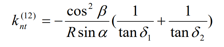
It can be seen from the above formula that as long as there is the same pressure angle on both sides of the tooth surface of spiral bevel gear pair, there is the same induced normal curvature.
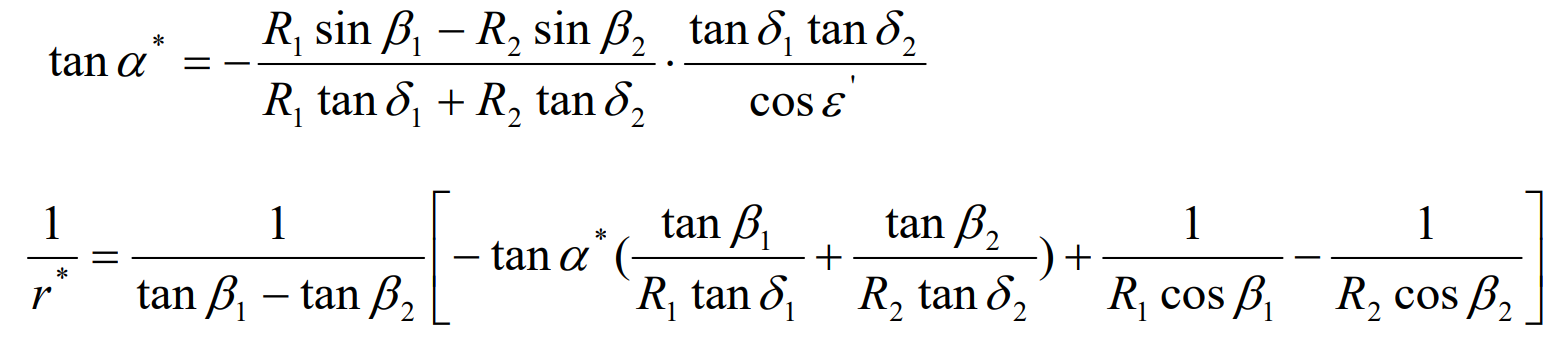
For Hypoid gear pairs, it is difficult to have the same induced normal curvature on both sides of the tooth surface because the cone tops of large and small bevel gears do not coincide. Now define the limit normal radius of curvature R * and the limit pressure angle α* In order to obtain the condition that the induced normal curvature on both sides of the gear pair teeth is the same. According to the gear meshing theory, when the conjugate surfaces envelope each other, there is a class II boundary line on the envelope surface that divides the envelope surface into two regions, one of which is the meshing region participating in the envelope and the other is the non meshing region not participating in the envelope. Generally, node P is a class II boundary point, so the pressure angle at node P is called the ultimate pressure angle α* , The radius of normal curvature at node P is called the limit radius of normal curvature R *. According to the gear meshing principle, the solution method of class II boundary points is known, so:
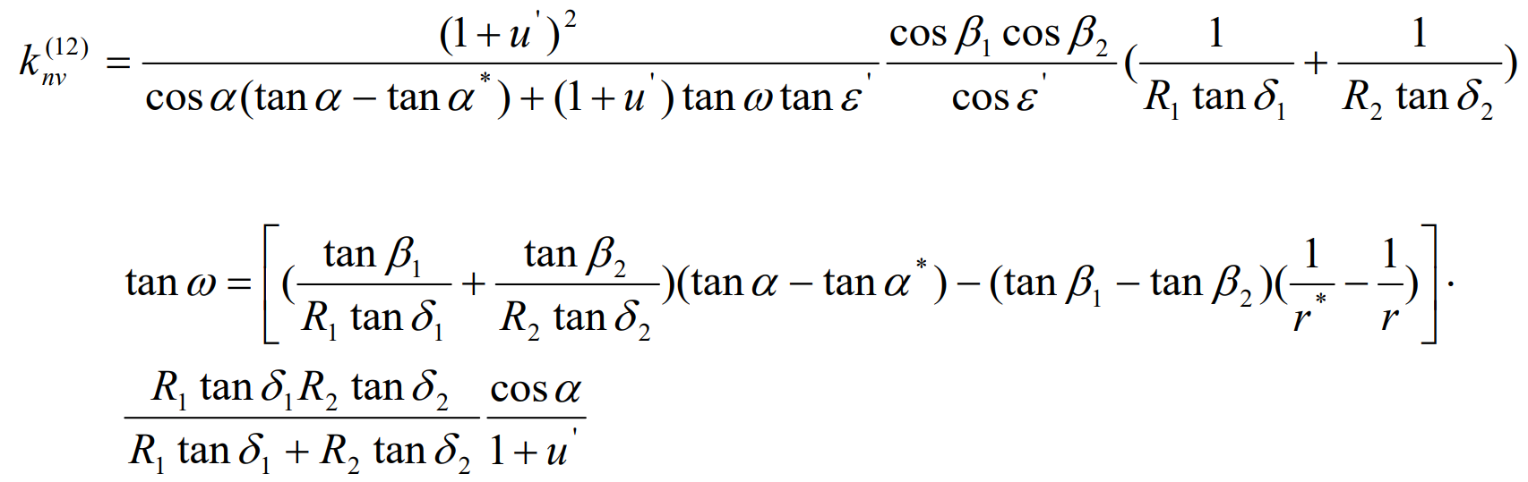
According to the above formula, the induced normal curvature K (12) Nv of hypoid gear pair along the tooth height direction and the direction angle of contact line ω Can be expressed as: