
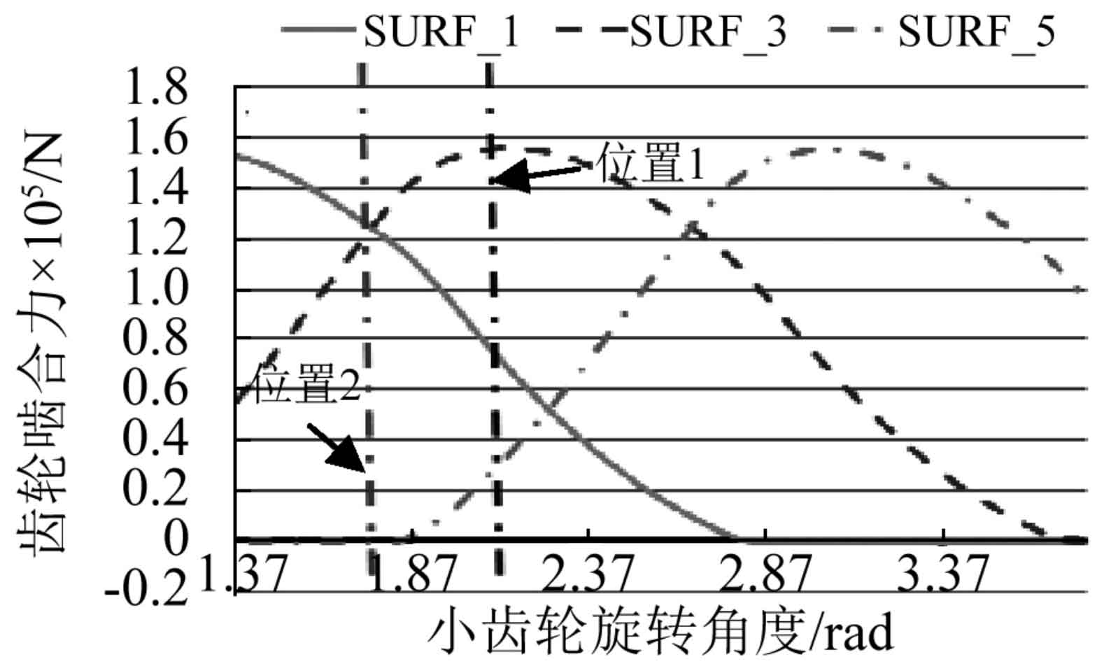
Then, the contact analysis of the gear under loading is carried out. The resistance moment applied at the output end of the large gear is 9000 n · m and the applied speed is 9.6 rad / s. as shown in Figure 1, the change process of single gear meshing force is surf_ The definition of I is the same as that in Figure 2. At the meshing position of position 1, it can be seen from the dotted line of the corresponding position in the figure that surf_ 1. The corresponding gear teeth are out of engagement, surf_ 5. The corresponding gear teeth enter into meshing. At this time, three gear teeth are in meshing. Similarly, position 2, surf, can be obtained_ 3 only two gears are engaged. Different from spur gears, because the direction of meshing force of hypoid gears changes with the rotation angle of gears, and the direction of meshing force of adjacent teeth in meshing at different times is different, the meshing force of all gears at any time cannot be simply added by the normal meshing force of meshing gears. Vector addition is required for the gear meshing force at the same time. Finally, the gear normal meshing force corresponding to any meshing time can be obtained as shown in Fig. 3. It can be seen from the figure that the magnitude of the meshing force changes periodically with the gear rotation.


The transmission error of large teeth is shown in Figure 4. It can be seen that the transmission error of gears changes periodically and also maintains a parabola shape. Compared with the transmission error of gears under small load, the transmission error of gears under large load translates downward accordingly, and the fluctuation of transmission error of gears under large load is smaller than that under small load. Because the tooth germ and tooth surface contact of the gear increase deformation under large load, the mean value of the transmission error increases, and the contact of the gear is more stable due to the increase of the loaded force, which reduces the fluctuation of the meshing error of the gear under large load.
The gear meshing stiffness can be obtained by substituting the data such as gear force, static transmission error and load transmission error into the formula. Fig. 5 shows the calculation results of meshing stiffness. From the figure, it can be seen that the meshing stiffness of the gear changes periodically. The change period of meshing stiffness is the same as that of gear meshing force and gear transmission error. This period is equal to the gear meshing period. The maximum gear meshing stiffness is selected as the starting point of meshing stiffness. The part between the two red dotted lines is an meshing cycle. In this cycle, the meshing stiffness of the gear first decreases, then basically maintains a constant size, then decreases slowly, finally rises rapidly, and then enters the next gear meshing cycle. Different from the change trend of stiffness in the meshing process of spur gear, the meshing stiffness of hypoid gear will not change suddenly, which can make the gear contact smoothly and reduce the meshing impact.

Compared with the change law of gear meshing stiffness when the load of gear is different. Here, the resistance torque of 1 000 n · m, 3 000 n · m, 5 000 n · m and 7 000 n · m respectively loaded on the big gear is compared with the resistance torque of 9 000 n · M input in the previous section. The comparison of stiffness calculation results is shown in Figure 6. It can be seen from the figure that with the increase of the loaded torque of the gear, the meshing stiffness of the gear increases and the fluctuation amplitude of meshing stiffness decreases. It is mainly due to the increase of gear loading force and the increase of gear meshing coincidence degree, which reduces the meshing impact during gear meshing. At the same time, the increase of meshing force increases the deformation of gear tooth germ and the average meshing stiffness.
