
I study the vibration and noise behavior of a logarithmic spiral bevel gear from the standpoint of meshing-in impact. In my analysis, the logarithmic spiral bevel gear is treated as a special spiral bevel gear whose tooth trace follows a logarithmic spiral. Because the spiral angle of this curve is constant along the tooth, the logarithmic spiral bevel gear can achieve equal-spiral-angle meshing. This geometric property is important for smooth transmission, but it does not remove the impact that occurs when a new pair of teeth enters contact. I therefore focus on the meshing-in impact force, because this force is one of the strongest sources of vibration and noise in a spiral bevel gear transmission.
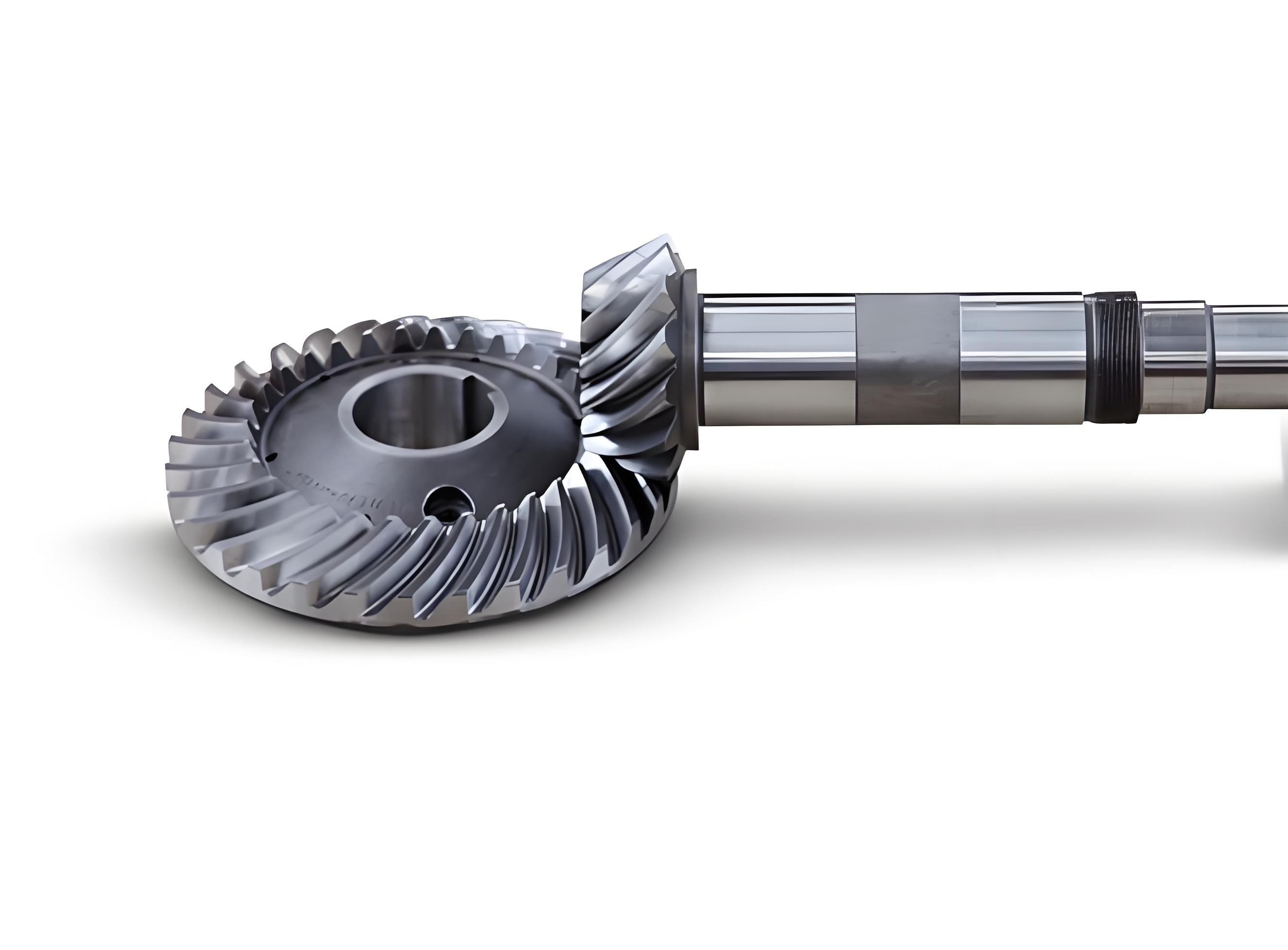
My starting point is the classical distinction between ideal meshing and actual meshing. In an ideal spiral bevel gear pair, the base pitches of the two gears are equal, so the contact point moves along the theoretical line of action without a sudden change in velocity. I write this condition as
$$P_{b1}=P_{b2}$$
where \(P_{b1}\) and \(P_{b2}\) are the base pitches of the driving and driven spiral bevel gears. In actual operation, manufacturing error, elastic deformation under load, and assembly deviation make the effective base pitches different. I represent this actual condition as
$$P_{b1}\neq P_{b2}$$
When this inequality appears, the two teeth do not reach the theoretical meshing point at the same time. The driving tooth enters contact earlier, while the driven tooth enters later. This produces a velocity difference at the contact point, and the velocity difference generates a meshing-in impact. In my study, I do not treat meshing-out impact as the main problem, because meshing-in impact is usually much larger in a spiral bevel gear. The reason is that the new tooth pair must suddenly share the load, and the elastic deformation of the previously loaded tooth pair changes the effective contact position.
To make the analysis quantitative, I first describe the tooth surface of the logarithmic spiral bevel gear. I use the following tooth profile equations:
$$
\begin{aligned}
r_b e^{\beta\theta}\cos\theta &= x\sin\phi – y\cos\phi,\\
0 &= x\cos\alpha\cos\phi + y\cos\alpha\sin\phi – z\sin\alpha,\\
\alpha &= \arcsin(\sin\beta\sin\gamma).
\end{aligned}
$$
In these equations, \(r_b\) is the base radius, \(\beta\) is the spiral angle, \(\theta\) is the central angle, \(\gamma\) is the pitch cone angle, \(\alpha\) is the base cone angle, and \(\phi\) is the position parameter of the gear. I use the position parameter to locate the contact point and to express the tooth surface in matrix form. For the first meshing tooth pair, the tooth profiles 1 and 2 can be written as
$$
\begin{bmatrix}
X_i\\
Y_i\\
Z_i
\end{bmatrix}
=
U_i V_i,\qquad i=1,2,
$$
where
$$
U_1 =
\begin{bmatrix}
-\cos\theta_1\cos\phi_1 & \sin\theta_1\sin\alpha_1\sin\phi_1 & 0\\
\cos\theta_1\sin\phi_1 & \sin\theta_1\sin\alpha_1\cos\phi_1 & 0\\
0 & 0 & \sin\theta_1\cos\phi_1
\end{bmatrix},
$$
$$
V_1 =
\begin{bmatrix}
r_b e^{\beta\theta_1}\\
r_b e^{\beta\theta_1}\\
r_b e^{\beta\theta_1}
\end{bmatrix},
$$
$$
U_2 =
\begin{bmatrix}
-\cos\theta_2\cos\phi_2 & \sin\theta_2\sin\alpha_2\sin\phi_2 & 0\\
\cos\theta_2\sin\phi_2 & \sin\theta_2\sin\alpha_2\cos\phi_2 & 0\\
0 & 0 & \sin\theta_2\cos\phi_2
\end{bmatrix},
$$
$$
V_2 =
\begin{bmatrix}
r_b e^{\beta\theta_2}\\
r_b e^{\beta\theta_2}\\
r_b e^{\beta\theta_2}
\end{bmatrix}.
$$
For the second meshing tooth pair, I define the tooth profiles 3 and 4 in the same way:
$$
\begin{bmatrix}
X_i\\
Y_i\\
Z_i
\end{bmatrix}
=
U_i V_i,\qquad i=3,4,
$$
with
$$
U_3 =
\begin{bmatrix}
-\cos\theta_3\cos\phi_3 & \sin\theta_3\sin\alpha_3\sin\phi_3 & 0\\
\cos\theta_3\sin\phi_3 & \sin\theta_3\sin\alpha_3\cos\phi_3 & 0\\
0 & 0 & \sin\theta_3\cos\phi_3
\end{bmatrix},
$$
$$
V_3 =
\begin{bmatrix}
r_b e^{\beta\theta_3}\\
r_b e^{\beta\theta_3}\\
r_b e^{\beta\theta_3}
\end{bmatrix},
$$
$$
U_4 =
\begin{bmatrix}
-\cos\theta_4\cos\phi_4 & \sin\theta_4\sin\alpha_4\sin\phi_4 & 0\\
\cos\theta_4\sin\phi_4 & \sin\theta_4\sin\alpha_4\cos\phi_4 & 0\\
0 & 0 & \sin\theta_4\cos\phi_4
\end{bmatrix},
$$
$$
V_4 =
\begin{bmatrix}
r_b e^{\beta\theta_4}\\
r_b e^{\beta\theta_4}\\
r_b e^{\beta\theta_4}
\end{bmatrix}.
$$
I use these matrix forms because they allow me to compare the coordinates of two adjacent tooth pairs. When the first tooth pair is already meshing, the second tooth pair approaches contact. The distance between the two approaching tooth surfaces tells me how close the second pair is to entering mesh. I define this distance as
$$d=\sqrt{(X_3-X_4)^2+(Y_3-Y_4)^2}.$$
For the first tooth pair, I impose the theoretical meshing condition:
$$
\begin{cases}
X_1=X_2,\\
Y_1=Y_2,\\
Y_1=X_1\tan\phi + r_{b1}.
\end{cases}
$$
This system contains the unknowns \(\theta_1\), \(\theta_2\), \(\phi_1\), and \(\phi_2\). Once I specify the position parameter of tooth profile 1, I can solve for the remaining unknowns. For the second tooth pair, I keep the central angles \(\theta_3=\theta_1\) and \(\theta_4=\theta_2\). The only unknown position parameters are \(\phi_3\) and \(\phi_4\). I search for the pair \((\phi_3^*,\phi_4^*)\) that makes \(d\) as small as possible. If \(d>0\), the second tooth pair has not yet entered mesh. If \(d=0\), the second tooth pair starts to enter mesh. In my calculation, I begin with a relatively large position parameter for the first tooth pair, and I gradually reduce it until \(d\) becomes zero. That instant is the meshing-in position of the logarithmic spiral bevel gear.
The meshing-in position is essential because it provides the geometric input for both meshing stiffness and impact velocity. I do not treat stiffness as a constant. Instead, I determine the meshing stiffness at the meshing-in point by using a finite element procedure together with the meshing theory. I import the three-dimensional model of the logarithmic spiral bevel gear into finite element software, assign material properties, define contact pairs, set boundary conditions, apply a load to the gear and a rotational speed to the pinion, and solve the contact problem. From the post-processing results, I extract the normal contact force \(F_s\) and the combined deformation \(\delta\) at the meshing-in point. I then fit the meshing stiffness as
$$K_s=\frac{F_s}{\delta}.$$
This definition is simple, but it is meaningful in my analysis because both \(F_s\) and \(\delta\) are obtained at the actual meshing-in position rather than at an arbitrary point on the tooth surface. The meshing stiffness of a spiral bevel gear is influenced by tooth geometry, contact position, load level, and boundary conditions. By using the finite element result at the meshing-in point, I preserve the local stiffness that controls the initial impact.
I also need the impact velocity. I derive the velocity of the driving and driven gears at the meshing-in point from the angular velocity vectors. Let the driving gear rotate about the \(k\)-axis and let the driven gear rotate about an axis inclined by the shaft angle \(\Sigma\). I write
$$
\omega_I=\omega_1\mathbf{k},
$$
$$
\omega_{II}=\omega_2\left(\sin\Sigma\,\mathbf{j}+\cos\Sigma\,\mathbf{k}\right).
$$
If the meshing-in point is \(M\), then the velocities of the two gears at \(M\) are
$$
V_I=\omega_I\times \mathbf{OM}
=
-\omega_1 y\,\mathbf{i}+\omega_1 x\,\mathbf{j},
$$
$$
V_{II}=\omega_{II}\times \mathbf{OM}
=
\omega_2(z\sin\Sigma-y\cos\Sigma)\mathbf{i}
+\omega_2 x\cos\Sigma\,\mathbf{j}
-\omega_2 x\sin\Sigma\,\mathbf{k}.
$$
The relative velocity at the meshing-in point is therefore
$$V_s=V_I-V_{II},$$
and its magnitude is
$$V_s=\|V_I-V_{II}\|.$$
This relative velocity is the impact velocity in my meshing-in impact model. I note that \(V_s\) depends on rotational speed, position of the meshing-in point, shaft angle, and gear ratio. Because the position of the meshing-in point itself depends on the tooth profile and the deformation state, the final impact velocity is coupled with the meshing stiffness. I handle this coupling by first determining the position parameter from the geometric approach, then evaluating the stiffness and velocity at that position.
Once the meshing stiffness and impact velocity are known, I calculate the impact force from impact mechanics and Hertz contact theory. I first compute the polar mass moment of inertia of each gear. For a hollow gear disk, I use
$$
J_1=\frac{\pi\rho b}{2}\left(r_{b1}^4-r_{h1}^4\right),
$$
$$
J_2=\frac{\pi\rho b}{2}\left(r_{b2}^4-r_{h2}^4\right),
$$
where \(\rho\) is the material density, \(b\) is the face width, \(r_{h1}\) and \(r_{h2}\) are the hub radii, and \(r_{b1}\) and \(r_{b2}\) are the base radii of the two gears. I then convert the rotational inertia into equivalent masses along the line of action:
$$
m_{e1}=\frac{J_1}{r_{b1}^2},
$$
$$
m_{e2}=\frac{J_2}{r_{b2}^2}.
$$
The effective mass of the meshing pair is
$$
m_e=\frac{m_{e1}m_{e2}}{m_{e1}+m_{e2}}
=
\frac{J_1J_2}{J_1r_{b2}^2+J_2r_{b1}^2}.
$$
The kinetic energy associated with the relative impact velocity is
$$E_k=\frac{1}{2}m_e V_s^2.$$
At the same time, the elastic energy stored during the contact deformation is
$$E_k=\int_0^\delta K_s x\,dx=\frac{1}{2}K_s\delta^2.$$
Equating the kinetic energy and the elastic energy gives
$$
\frac{1}{2}m_e V_s^2=\frac{1}{2}K_s\delta^2,
$$
so the combined deformation at the meshing-in point is
$$
\delta=V_s\sqrt{\frac{m_e}{K_s}}.
$$
Because the impact force is related to the deformation by
$$F_s=K_s\delta,$$
I obtain the final expression for the meshing-in impact force of the logarithmic spiral bevel gear:
$$
F_s
=
V_s\sqrt{K_s m_e}
=
V_s\sqrt{
K_s
\frac{J_1J_2}{J_1r_{b2}^2+J_2r_{b1}^2}
}.
$$
This expression is the core of my theoretical model. It shows that the meshing-in impact force of a spiral bevel gear increases with the relative impact velocity \(V_s\), increases with the meshing stiffness \(K_s\), and depends on the inertia distribution through the term \(J_1J_2/(J_1r_{b2}^2+J_2r_{b1}^2)\). I also observe that the impact force is not simply proportional to speed or load alone. It is a coupled function of geometry, stiffness, inertia, and velocity.
| Symbol | Meaning |
|---|---|
| \(Z_1, Z_2\) | Numbers of teeth of the driving and driven spiral bevel gears |
| \(\gamma_1, \gamma_2\) | Pitch cone angles |
| \(m\) | Large-end module |
| \(d_1, d_2\) | Pitch diameters |
| \(\beta\) | Spiral angle |
| \(b\) | Face width |
| \(h_a, h_f\) | Addendum and dedendum |
| \(\Sigma\) | Shaft angle |
| \(\rho\) | Material density |
| \(r_h\) | Hub inner radius |
| \(r_b\) | Base radius |
| \(\alpha\) | Base cone angle |
| \(\theta\) | Central angle |
| \(\phi\) | Position parameter |
| \(K_s\) | Meshing stiffness at the meshing-in point |
| \(\delta\) | Combined deformation at the meshing-in point |
| \(V_s\) | Relative impact velocity |
| \(F_s\) | Meshing-in impact force |
To test the model, I calculate a typical logarithmic spiral bevel gear pair. The geometric and material parameters are listed in the table below. I use these values to determine the meshing-in position, the meshing stiffness, the impact velocity, and finally the impact force.
| Parameter | Value |
|---|---|
| Tooth number | \(Z_1=15,\; Z_2=28\) |
| Pitch cone angle | \(\gamma_1=28^\circ 11′,\; \gamma_2=61^\circ 49’\) |
| Large-end module | \(m=6\;\text{mm}\) |
| Pitch diameter | \(d_1=90\;\text{mm},\; d_2=168\;\text{mm}\) |
| Spiral angle | \(\beta=39^\circ 52’\) |
| Face width | \(b=29\;\text{mm}\) |
| Addendum | \(h_a=4.2\;\text{mm}\) |
| Dedendum | \(h_f=5.4\;\text{mm}\) |
| Shaft angle | \(\Sigma=90^\circ\) |
| Density | \(\rho=7.83\times 10^{-9}\;\text{t/mm}^3\) |
| Hub inner radius | \(r_{h1}=7\;\text{mm},\; r_{h2}=10\;\text{mm}\) |
| Base radius | \(r_{b1}=84.57\;\text{mm},\; r_{b2}=157.87\;\text{mm}\) |
For the driving gear speed \(\omega_1=800\;\text{r/min}\), I obtain a relative impact velocity \(V_s=84\;\text{m/min}\). Using the finite element contact solution at the meshing-in point, I obtain the meshing stiffness \(K_s=81432\;\text{N/mm}\). Substituting these values into my impact force expression gives \(F_s=12.7\;\text{kN}\). I also perform an ABAQUS simulation of the same logarithmic spiral bevel gear pair. The simulated maximum meshing-in impact force is \(13.0\;\text{kN}\). The difference between the analytical result and the simulation is about \(2.3\%\). This agreement supports the correctness of my derivation and shows that the analytical expression captures the dominant physical behavior of the spiral bevel gear impact.
| Quantity | Value |
|---|---|
| Driving gear speed | \(\omega_1=800\;\text{r/min}\) |
| Relative impact velocity | \(V_s=84\;\text{m/min}\) |
| Meshing stiffness | \(K_s=81432\;\text{N/mm}\) |
| Analytical impact force | \(F_s=12.7\;\text{kN}\) |
| Simulated maximum impact force | \(F_s=13.0\;\text{kN}\) |
| Relative error | \(2.3\%\) |
I then examine how the impact force changes with rotational speed. I keep the load at \(1000\;\text{N}\) and increase the driving speed from a low value to a higher value. The analytical and numerical results are compared in the following table. I observe that the meshing-in impact force increases with speed, and the increase is approximately linear. This linear trend is consistent with my formula, because the impact force is directly proportional to \(V_s\), provided that the stiffness and effective mass do not change strongly over the speed range considered.
| Speed parameter | Analytical force (N) | ABAQUS force (N) | Error |
|---|---|---|---|
| 300 | 3430 | 3211 | 5.2% |
| 500 | 6920 | 6641 | 4.0% |
| 600 | 13430 | 12900 | 4.0% |
| 800 | 15800 | 14981 | 5.1% |
The effect of gear ratio is also important. I vary the transmission ratio \(i=Z_2/Z_1\) while keeping the load and speed fixed. I find that the meshing-in impact force reaches a maximum when the transmission ratio is equal to one. When \(i=1\), the two spiral bevel gears have similar inertia and similar base radii, and the relative velocity and effective mass combine to produce the largest impact. When the ratio moves away from one, the effective inertia distribution becomes less favorable for impact, and the impact force decreases. This result is useful for design because it suggests that a logarithmic spiral bevel gear pair with a ratio close to one requires more attention to impact control, tooth modification, or damping.
| Transmission ratio \(i\) | Relative impact trend |
|---|---|
| \(i=0.5\) | Lower than maximum |
| \(i=1.0\) | Maximum impact |
| \(i=2.0\) | Reduced impact |
| \(i=3.0\) | Further reduced impact |
| \(i=4.0\) | Low impact |
| \(i=5.0\) | Low impact |
| \(i=6.0\) | Low impact |
I next study the influence of face width. I keep the speed and load constant and change the face width of the logarithmic spiral bevel gear. The results are listed below. As the face width increases, the impact force increases almost proportionally. This happens because the polar mass moment of inertia is proportional to the face width, and the effective mass also increases with the face width. In my formula, the effective mass term grows with \(b\), so the impact force grows with \(b\) as well. This result is important because increasing face width is often used to improve load capacity, but my analysis shows that it can also increase meshing-in impact unless the tooth contact pattern and stiffness are properly controlled.
| Face width (mm) | Analytical force (N) | ABAQUS force (N) | Error |
|---|---|---|---|
| 20 | 11000 | 10528 | 4.2% |
| 40 | 22000 | 21263 | 3.3% |
| 60 | 33000 | 32010 | 3.0% |
| 80 | 44000 | 42892 | 3.0% |
| 100 | 55000 | 53001 | 3.6% |
For the simulation verification, I use ABAQUS as the finite element solver. I import the three-dimensional model of the logarithmic spiral bevel gear into Hypermesh for mesh generation. Because the tooth surface of a logarithmic spiral bevel gear is complex, the automatic meshing capability of ABAQUS alone is not sufficient for my purpose. Hypermesh gives me better control over the tooth surface mesh, the contact region, and the transition zones. To reduce computation time, I extract one meshing tooth pair from the full gear pair. When the gear first enters mesh, the contact point is located in the single-tooth contact region, so a one-tooth-pair model is sufficient to capture the initial impact behavior without changing the main conclusion.
I define the material of the logarithmic spiral bevel gear as 20CrMnTi steel. The material properties are listed below. I use a density of \(7.8\times 10^{-9}\;\text{t/mm}^3\), an elastic modulus of \(210000\;\text{MPa}\), and a Poisson ratio of \(0.3\). The hardness range is 58-63 HRC, which is typical for a heavily loaded spiral bevel gear.
| Material property | Value |
|---|---|
| Elastic modulus | \(210000\;\text{MPa}\) |
| Poisson ratio | 0.3 |
| Density | \(7.8\times 10^{-9}\;\text{t/mm}^3\) |
For contact definition, I use a surface-to-surface contact formulation. The normal behavior is hard contact, and the tangential behavior uses a penalty friction model with a friction coefficient of 0.1. I allow finite sliding because the contact point moves along the tooth surface during meshing. Since both gears are made of the same material, I select the pinion as the master surface and the gear as the slave surface. The pinion has a finer mesh, so this choice improves contact resolution.
| Contact parameter | Setting |
|---|---|
| Contact type | Surface-to-surface |
| Normal behavior | Hard contact |
| Tangential behavior | Penalty friction |
| Friction coefficient | 0.1 |
| Sliding formulation | Finite sliding |
| Master surface | Pinion tooth surface |
| Slave surface | Gear tooth surface |
I apply the boundary conditions and initial conditions through a reference point on the gear axis. The reference point is coupled to the gear body, so the rotational speed and torque can be applied to the coupling nodes. This approach is necessary because the rotational degree of freedom of a solid element in ABAQUS is not directly available in the same way as in a rigid body. By using a kinematic coupling, I simulate the shaft connection and apply the initial angular velocity to the driving spiral bevel gear while keeping the driven gear initially stationary. The relative velocity at the meshing-in point then becomes the impact velocity in the simulation.
After solving the finite element model, I extract the contact force history and identify the maximum value during the meshing-in event. The simulated impact force curve shows a short transient peak, which is the meshing-in impact of the logarithmic spiral bevel gear. I compare this peak with the analytical prediction. For the baseline case, the analytical result is \(12.7\;\text{kN}\), and the ABAQUS result is \(13.0\;\text{kN}\). The relative error is \(2.3\%\). For different speeds and face widths, the error remains within a small range, as shown in the tables above. These comparisons give me confidence that the analytical model is reliable for engineering estimation of the meshing-in impact of a spiral bevel gear.
| Case | Analytical force | ABAQUS force | Error |
|---|---|---|---|
| Baseline \(800\;\text{r/min}\) | \(12.7\;\text{kN}\) | \(13.0\;\text{kN}\) | 2.3% |
| Speed 300 | \(3.43\;\text{kN}\) | \(3.211\;\text{kN}\) | 5.2% |
| Speed 500 | \(6.92\;\text{kN}\) | \(6.641\;\text{kN}\) | 4.0% |
| Speed 600 | \(13.43\;\text{kN}\) | \(12.90\;\text{kN}\) | 4.0% |
| Speed 800 | \(15.80\;\text{kN}\) | \(14.981\;\text{kN}\) | 5.1% |
| Face width \(20\;\text{mm}\) | \(11.00\;\text{kN}\) | \(10.528\;\text{kN}\) | 4.2% |
| Face width \(40\;\text{mm}\) | \(22.00\;\text{kN}\) | \(21.263\;\text{kN}\) | 3.3% |
| Face width \(60\;\text{mm}\) | \(33.00\;\text{kN}\) | \(32.010\;\text{kN}\) | 3.0% |
| Face width \(80\;\text{mm}\) | \(44.00\;\text{kN}\) | \(42.892\;\text{kN}\) | 3.0% |
| Face width \(100\;\text{mm}\) | \(55.00\;\text{kN}\) | \(53.001\;\text{kN}\) | 3.6% |
My results lead to several conclusions about the logarithmic spiral bevel gear. The meshing-in impact is controlled by the relative impact velocity, the meshing stiffness at the entry point, and the effective inertia of the meshing pair. The impact velocity has a strong influence on the impact force. Because the impact force is approximately proportional to the impact velocity, reducing the relative velocity is one of the most direct ways to reduce vibration and noise in a spiral bevel gear transmission. The face width also has a strong influence. Increasing the face width increases the impact force almost linearly, so a wider spiral bevel gear is not automatically quieter. The transmission ratio has a non-monotonic effect. When the ratio is one, the impact force is largest, while ratios away from one tend to reduce the impact. This finding is useful for matching a logarithmic spiral bevel gear pair to a given application.
I also conclude that the analytical model is practical. It requires the tooth profile equations, the meshing-in position, the local meshing stiffness, and the relative impact velocity. All of these quantities can be obtained from geometry, finite element contact analysis, and kinematic relations. The model does not require a full transient simulation for every design change, so it can be used for rapid screening of a logarithmic spiral bevel gear design. Once a promising design is found, a full finite element simulation can be used to verify the maximum impact force and the contact stress.
From the simulation side, I find that ABAQUS is an effective tool for studying the dynamic behavior of a logarithmic spiral bevel gear. The combination of Hypermesh for meshing and ABAQUS for contact and explicit dynamics allows me to capture the short impact transient. The reference-point coupling method provides a convenient way to apply rotational speed and torque to the spiral bevel gear. The surface-to-surface contact with hard normal behavior and penalty friction gives stable results for the meshing-in event. The numerical results agree with the analytical model within a few percent, which validates both the theoretical derivation and the finite element procedure.
For future work, I would extend the model in several directions. One direction is to include the effect of tooth modification and manufacturing error on the meshing-in position. Another direction is to study the interaction between meshing-in impact and meshing-out impact over a full meshing cycle. A third direction is to optimize the logarithmic spiral bevel gear parameters, such as spiral angle, pressure angle, and face width, to minimize the meshing-in impact while maintaining load capacity. A fourth direction is to include the dynamic response of the shafts and bearings, because the gear pair does not operate in isolation. These extensions would make the model even more useful for quiet and reliable spiral bevel gear design.
In summary, I have developed a theoretical and numerical study of the meshing-in impact of a logarithmic spiral bevel gear. I derived the tooth profile equations, determined the meshing-in point by an approximation method, obtained the meshing stiffness from finite element contact analysis, derived the relative impact velocity from the angular velocity relation, and formulated the meshing-in impact force from impact mechanics and Hertz contact theory. I then calculated a typical logarithmic spiral bevel gear pair and compared the analytical results with ABAQUS simulations. The agreement is good, and the parametric study shows that speed and face width strongly affect the impact force, while the transmission ratio has a maximum effect at unity. These findings provide a quantitative basis for reducing vibration and noise in a logarithmic spiral bevel gear transmission.