
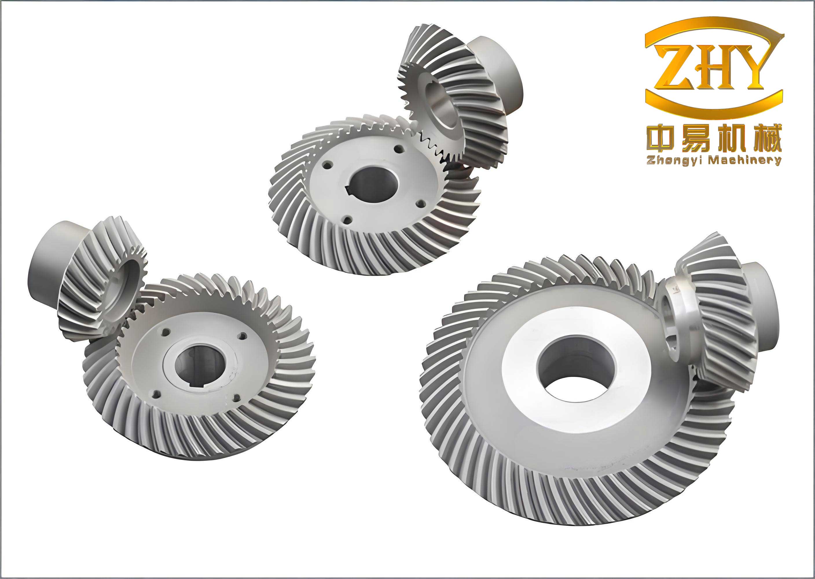
As an engineer specializing in automotive drivetrain systems, I have spent considerable time studying the lubrication challenges associated with hyperbolic gears. These gears, commonly used in automotive drive axles, operate under severe conditions due to high contact stresses and significant sliding motions. The lubrication of hyperbolic gears is not merely about reducing friction; it is a critical factor in preventing failure, minimizing noise, and ensuring longevity. In this article, I will delve into the intricacies of hyperbolic gears lubrication, drawing from theoretical principles and practical experiences. We will explore gear damage mechanisms, lubrication theories, selection criteria, and operational considerations, all while emphasizing the unique aspects of hyperbolic gears. Throughout, I will incorporate formulas and tables to summarize key points, and as a visual aid, I include an image that illustrates the complex geometry of hyperbolic gears.
The primary goal of lubricating hyperbolic gears is to form a protective film between mating surfaces, thereby preventing direct metal-to-metal contact. This film must withstand extreme pressures and temperatures while accommodating the sliding and rolling actions inherent in hyperbolic gears. The lubrication serves multiple purposes: it reduces wear and friction, dissipates heat, dampens vibrations and shocks, prevents corrosion, and cleans contaminants from the gear mesh. In drive axles, the lubricant often serves the entire assembly, including bearings, making its selection even more crucial. Hyperbolic gears, with their offset pinion and curved tooth profiles, present a unique lubrication challenge compared to other gear types. The sliding velocities in hyperbolic gears can be substantial, especially away from the pitch line, leading to a high risk of scuffing or scoring if the lubrication is inadequate.
Gear damage in hyperbolic gears can manifest in various forms, broadly categorized by organizations like the American Gear Manufacturers Association (AGMA). Common failure modes include scuffing, pitting, spalling, and fatigue fractures. For hyperbolic gears, scuffing and pitting are particularly prevalent due to the high sliding speeds and contact stresses. Scuffing occurs when the lubricant film breaks down, causing localized welding and tearing of surfaces, often visible as streaks in the sliding direction. Pitting, on the other hand, results from cyclic contact stresses that initiate micro-cracks, leading to surface material removal. The occurrence of these damages depends on load and sliding speed regimes; for hyperbolic gears, scuffing is more likely in high-sliding-speed regions, while pitting dominates under high-load conditions. To systematically understand gear damage, I summarize the AGMA classification in the table below.
| Damage Type | Description | Common Causes in Hyperbolic Gears |
|---|---|---|
| Scuffing (Adhesive Wear) | Localized welding and tearing due to lubricant film failure | High sliding speeds, inadequate lubricant film thickness |
| Pitting (Surface Fatigue) | Formation of pits from cyclic stress-induced cracks | High contact stresses, lubricant contamination |
| Spalling | Large-scale material removal from subsurface cracks | Overload, material defects |
| Abrasive Wear | Material removal by hard particles | Contaminated lubricant, poor filtration |
| Plastic Yield | Permanent deformation under load | Excessive loads, insufficient hardness |
Preventing such damage in hyperbolic gears requires a deep understanding of the lubrication regime. The contact between hyperbolic gear teeth is typically elliptical, as shown in the image above, and the sliding conditions vary along the tooth profile. The relative sliding velocity is minimal at the pitch line and increases away from it. For hyperbolic gears, the sliding velocity components can be derived mathematically. Let us consider a pinion and gear pair with specific geometric parameters. The absolute sliding velocity on the pinion side in the lengthwise direction, $v_{s,p,L}$, and profile direction, $v_{s,p,P}$, are given by:
$$v_{s,p,L} = R_m \omega_p \left[ \sin(\phi_n) \cos(\psi) \left( \frac{\tan(\delta_p)}{\cos(\psi)} – \frac{x}{R_m} \right) + \cos(\phi_n) \sin(\psi) \left( \frac{\tan(\delta_p)}{\cos(\psi)} – \frac{x}{R_m} \right) \right]$$
$$v_{s,p,P} = \frac{R_m \omega_p \sin(\phi_n) \sin(\psi)}{\cos(\delta_p)} \left( \frac{\tan(\delta_p)}{\cos(\psi)} – \frac{x}{R_m} \right)$$
Similarly, for the gear side, the velocities are:
$$v_{s,g,P} = R_m \omega_p \left[ \sin(\phi_n) \cos(\psi) \left( \frac{\tan(\delta_g)}{\cos(\psi)} + \frac{x}{R_m} \right) – \cos(\phi_n) \sin(\psi) \left( \frac{\tan(\delta_g)}{\cos(\psi)} + \frac{x}{R_m} \right) \right]$$
$$v_{s,g,L} = \frac{R_m \omega_p \sin(\phi_n) \sin(\psi)}{\cos(\delta_g)} \left( \frac{\tan(\delta_g)}{\cos(\psi)} + \frac{x}{R_m} \right)$$
The resultant sliding speed, $v_s$, is the vector sum of these components. Here, $R_m$ is the mean cone distance, $\omega_p$ is the pinion angular velocity, $x$ is the distance from the pitch point, $\delta_p$ and $\delta_g$ are the pinion and gear pitch angles, $\psi$ is the spiral angle, and $\phi_n$ is the normal pressure angle. These equations highlight the complex kinematics of hyperbolic gears, where sliding is inherent and lubrication must accommodate varying speeds across the tooth surface. The contact stress, $\sigma_c$, in hyperbolic gears is another critical parameter, calculated using the Hertzian contact theory for elliptical contacts:
$$\sigma_c = \frac{2}{\pi} \sqrt{\frac{E’ P_t}{L’ \rho_n}} \cdot K_c$$
where $E’$ is the effective elastic modulus, $P_t$ is the tangential dynamic load per tooth, $L’$ is the effective length of contact line, $\rho_n$ is the relative radius of curvature in the profile direction, and $K_c$ is a contact condition factor. For hyperbolic gears, the elliptical contact area means that the pressure distribution is non-uniform, and the minimum film thickness, $h_0$, can be estimated using elastohydrodynamic lubrication (EHL) theory. For an elliptical contact with constant viscosity, the pressure distribution $p(x,y)$ is given by:
$$p(x,y) = \frac{3}{2} \frac{W}{\pi a b} \left(1 – \frac{x^2}{a^2} – \frac{y^2}{b^2}\right)^{1/2}$$
where $W$ is the load, $a$ and $b$ are the semi-axes of the contact ellipse. The film thickness equation, considering viscosity-pressure effects, is:
$$h_0 = \frac{2.65 \alpha^{0.54} (\eta_0 v_s)^{0.7} R^{0.43}}{E’^{0.03} W^{0.13}}$$
Here, $\alpha$ is the pressure-viscosity coefficient, $\eta_0$ is the dynamic viscosity at ambient pressure, $v_s$ is the sliding speed, $R$ is the effective radius of curvature, and $E’$ is the effective elastic modulus. When $h_0$ falls below the composite surface roughness, scuffing risk increases dramatically. This underscores the importance of maintaining adequate lubricant film thickness in hyperbolic gears, especially under high-load and high-sliding conditions.
Selecting the right lubricant for hyperbolic gears involves balancing several factors: viscosity, extreme pressure (EP) additives, base oil quality, and detergency. The lubricant must provide sufficient film strength while minimizing power losses and thermal degradation. Viscosity plays a pivotal role; higher viscosity generally enhances film thickness but increases churning losses and operating temperatures. For hyperbolic gears, typical viscosity grades are SAE 75W-90 or SAE 80W-140, with multi-grade oils becoming more common for wider temperature ranges. The effect of viscosity on load-carrying capacity can be summarized in the table below, based on experimental data from test machines like the Timken tester.
| Viscosity Grade | Film Thickness Trend | Scuffing Resistance | Temperature Rise |
|---|---|---|---|
| SAE 75W-90 | Moderate | Good for mild conditions | Lower |
| SAE 80W-140 | High | Excellent for severe conditions | Higher due to churning |
| Multi-grade (e.g., 75W-140) | Balanced across temperatures | Very good | Moderate |
Extreme pressure additives are crucial for hyperbolic gears because they form protective films on metal surfaces under high pressure and temperature. Common EP additives include sulfur-phosphorus (S-P) types, which react with surfaces to create iron sulfides and phosphates that prevent welding. However, excessive EP additives can lead to corrosion or reduce fatigue life. The concentration of EP additives must be optimized based on the severity of operation. For instance, in high-offset hyperbolic gears used in performance vehicles, higher EP levels (e.g., API GL-5) are recommended, whereas standard applications might use API GL-4. The effectiveness of EP additives depends on sliding speed; as speed increases, the chemical reaction rates change, altering the film formation. This relationship can be expressed as:
$$\text{EP Effectiveness} = k \cdot [\text{Additive}]^{n} \cdot v_s^{-m}$$
where $k$, $n$, and $m$ are constants specific to the additive chemistry, $[\text{Additive}]$ is the concentration, and $v_s$ is the sliding speed. Base oil quality and detergents also influence performance. Highly refined base oils with low sulfur content provide better oxidation stability, but may require more EP additives. Detergents, used to control deposits, can interfere with EP film formation if overused. Therefore, lubricant formulation for hyperbolic gears is a delicate balance, often tailored to specific gear designs and operating conditions.
In practice, the lubrication of hyperbolic gears in drive axles is typically via oil bath systems. The oil level must be carefully controlled: too high, and churning losses increase, leading to overheating and oil degradation; too low, and starvation occurs, causing inadequate cooling and lubrication. For hyperbolic gears, the oil level should at least cover the gear teeth when stationary, but considerations for bearing lubrication often dictate higher levels. During operation, oil sloshing and foaming can occur, especially in hypoid axles with large offsets, so anti-foam agents are sometimes added. The recommended oil volume, $V$, for a drive axle with hyperbolic gears can be estimated as:
$$V = A \cdot h + V_{\text{bearings}}$$
where $A$ is the sump area, $h$ is the oil height above the gear, and $V_{\text{bearings}}$ is the additional volume needed for bearing immersion. Operating temperature, $T_{\text{op}}$, should be monitored, as it affects viscosity and additive performance. A simple thermal model gives:
$$T_{\text{op}} = T_{\text{amb}} + \frac{P_{\text{loss}}}{k_{\text{cool}} A_{\text{cool}}}$$
where $T_{\text{amb}}$ is ambient temperature, $P_{\text{loss}}$ is power loss from gear meshing and churning, $k_{\text{cool}}$ is the cooling coefficient, and $A_{\text{cool}}$ is the cooling surface area. Maintaining $T_{\text{op}}$ below 120°C is advisable for most hyperbolic gears lubricants to prevent rapid oxidation.
Oil change intervals for hyperbolic gears depend on service conditions. Initial break-in periods are critical, as wear debris from manufacturing and run-in can contaminate the oil. Typically, the first oil change is recommended at 5,000 km for new hyperbolic gears assemblies. Thereafter, intervals extend based on usage; for severe duty (e.g., towing, high-speed driving), changes may be needed every 50,000 km, while normal service might allow up to 100,000 km. Water ingress, oxidation, and additive depletion are key factors necessitating changes. The following table summarizes oil change practices for hyperbolic gears in various automotive applications.
| Vehicle Type | Typical Oil Change Interval (Normal Service) | Severe Service Interval | Recommended Lubricant Grade |
|---|---|---|---|
| Passenger Cars with Hyperbolic Gears | 100,000 km or lifetime fill | 50,000 km | API GL-5, SAE 75W-90 |
| Light Trucks with Hyperbolic Gears | 80,000 km | 40,000 km | API GL-5, SAE 80W-140 |
| Heavy-Duty Trucks with Hyperbolic Gears | 60,000 km | 30,000 km | API GL-5, SAE 85W-140 |
Looking ahead, the lubrication of hyperbolic gears faces evolving challenges. Modern trends toward higher gear offsets and improved tooth geometries for noise reduction impose stricter demands on lubricants. For instance, high-offset hyperbolic gears exhibit increased sliding velocities, raising scuffing risks. Future lubricants may need advanced polymer thickeners or nano-additives to enhance film strength without compromising efficiency. Additionally, the integration of electric vehicles (EVs) introduces new conditions: hyperbolic gears in EV axles often experience higher torque at low speeds, requiring lubricants with better extreme pressure performance at lower temperatures. Research into synthetic base oils, such as polyalphaolefins (PAOs), shows promise for hyperbolic gears due to their stable viscosity-temperature characteristics and low volatility.
In conclusion, the lubrication of hyperbolic gears is a multifaceted discipline blending mechanical engineering, tribology, and chemistry. From understanding the kinematic equations governing sliding velocities to selecting the optimal blend of viscosity and EP additives, every detail matters. Hyperbolic gears, with their unique geometry and operating conditions, demand careful lubrication strategies to prevent failures like scuffing and pitting. Through continued innovation in lubricant formulations and gear design, we can enhance the durability and efficiency of hyperbolic gears in automotive applications. As we push the boundaries of performance, the role of lubrication will only grow in importance, ensuring that hyperbolic gears continue to transmit power smoothly and reliably.