
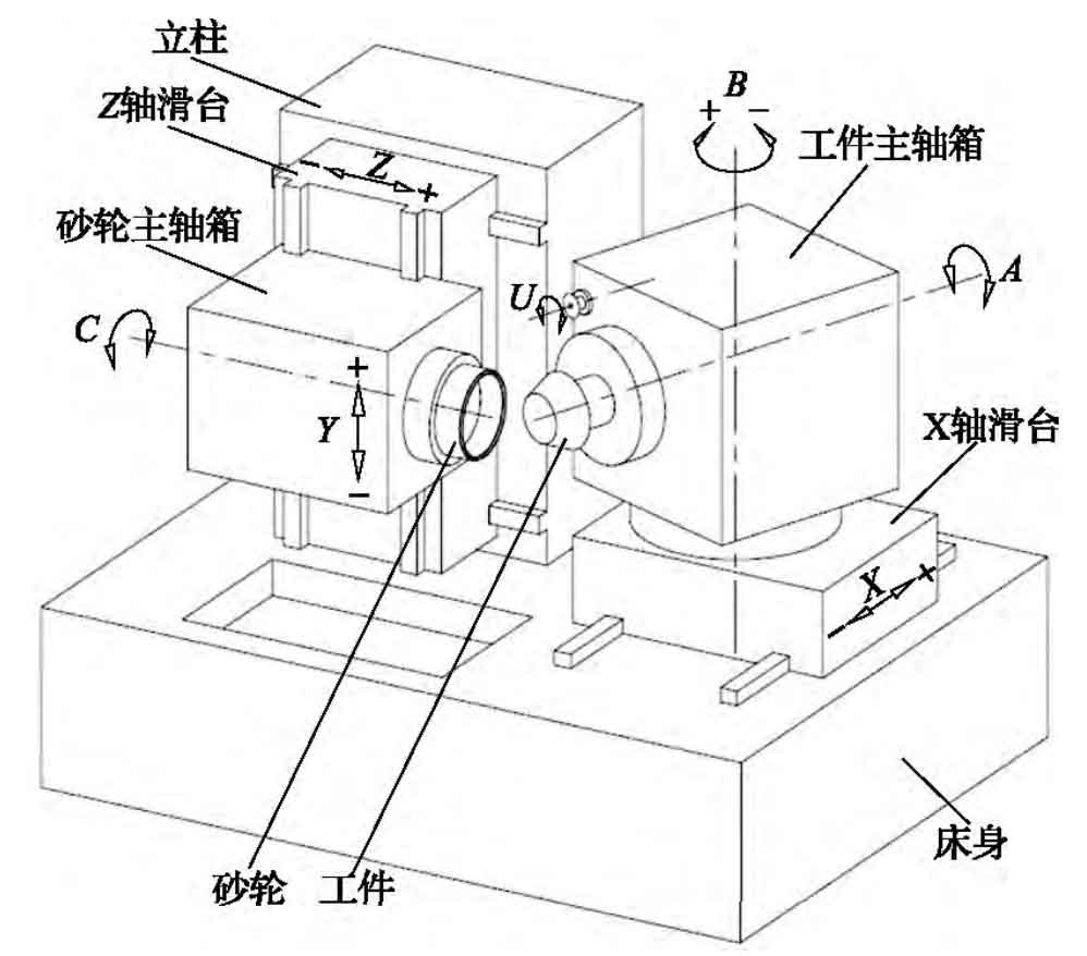
The figure is the machine tool model diagram of h350g CNC spiral bevel gear grinding machine. The linear axis X realizes the forward and backward movement of the workpiece spindle box, the linear axis Y realizes the up and down movement of the grinding wheel spindle box, and the linear axis Z realizes the left and right movement of the grinding wheel spindle box. Rotating shaft a is the rotating shaft of the workpiece, rotating shaft c is the rotating shaft of the grinding wheel, and rotating shaft B is the rotating shaft for adjusting the included angle between the workpiece axis and the grinding wheel axis.
In order to realize the on-machine measurement of tooth profile error and automatic tool setting of workpiece, an on-machine measurement device is installed on the grinding wheel spindle box. When measuring the tooth profile error of spiral bevel gear, the probe extends from the grinding wheel spindle box driven by hydraulic cylinder (the extension direction is parallel to the axis line of grinding wheel spindle). In addition, in order to calibrate the spatial coordinates of the probe ball center in the machine tool coordinate system, a probe calibration block (not shown in the figure) is installed on the workpiece spindle box.
In order to determine the position of each NC axis and the ball center of the probe in the machine tool space, the following machine tool coordinate system is established: when the axis of rotating axis C and the axis of rotating axis a are in the same horizontal plane, the intersection of the axis of rotating axis C and the axis of rotating axis B is the origin of the machine tool coordinate system, and the definitions and positive and negative directions of the three linear axes x, y and Z are shown in Figure 1.
The tooth surface of spiral bevel gear is a spatial complex curved surface. When measuring the tooth profile error of the actual tooth surface relative to the theoretical design tooth surface, it is necessary to control the probe to approach the actual tooth surface along the normal vector direction of each discrete point of the theoretical tooth surface. When the probe is triggered, the tooth profile error value is calculated according to the spatial coordinates of the ball center. When measuring the tooth profile error of different discrete points, different points on the spherical surface of the measuring ball are in contact with the actual tooth surface. Therefore, in order to ensure the measurement accuracy, the measuring head needs to have consistent pre travel error in different measurement directions, and the pre travel error should be as small as possible. Therefore, the mp250 strain gauge trigger probe produced by Renishaw company is selected to build the on-machine measurement system. The probe has compact structure and low contact force. It is suitable for submicron precision measurement of three-dimensional complex curved surface, and the maximum repeatability error is only 0.25 μ m. The pre travel error of the probe in three-dimensional space is less than 1 μ m。 The measuring accuracy of the probe itself meets the requirements of on-machine measurement of spiral bevel gear tooth profile error.