
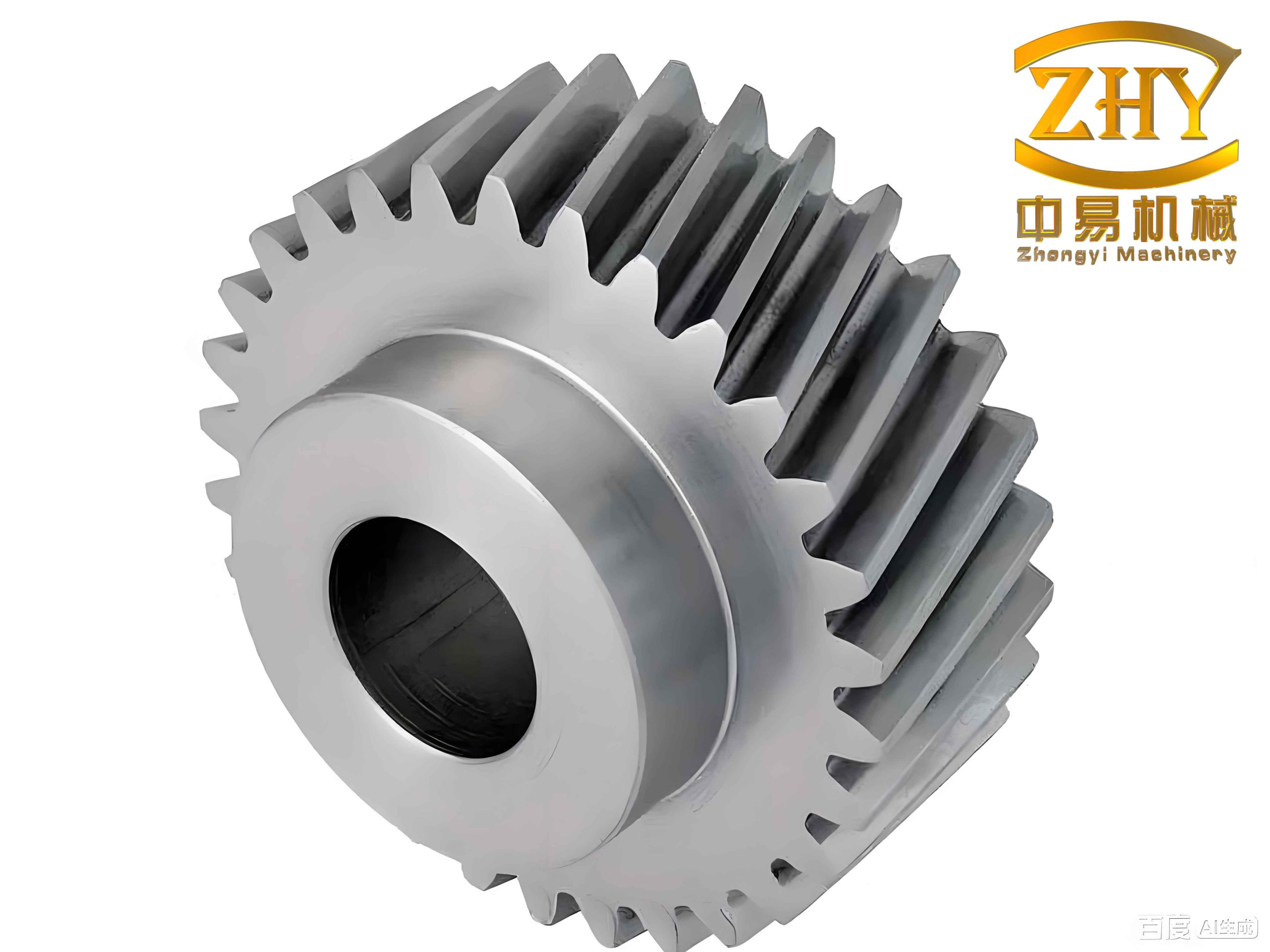
I have focused my research on a non-contact measurement method for helical gear parameter inspection using machine vision. A helical gear is widely used in mechanical transmission because its teeth engage progressively, which gives it advantages over a spur gear in transmission smoothness, load capacity, vibration, and noise. In industrial applications such as automotive manufacturing, the accurate inspection of a helical gear is essential for ensuring transmission performance, service life, and assembly quality. Traditional contact measurement methods for helical gear parameters often require specialized instruments, long measurement times, and direct contact with the tooth surface. These methods can damage the surface of a helical gear, are difficult to use for online inspection, and depend heavily on operator skill. To overcome these limitations, I developed a dual-camera machine vision method that measures end-face and side-face parameters of a helical gear simultaneously. The method provides high-precision, non-contact, and automated inspection of a helical gear.
The main parameters that I measure include the addendum circle diameter, dedendum circle diameter, inner hole diameter, number of teeth, helix angle, hand of helix, and concentricity error. I use two cameras: one camera views the end face of the helical gear, and the other views the side face. The end-face camera is used to extract the addendum circle, dedendum circle, inner hole, tooth count, and concentricity. The side-face camera is used to extract the helix angle and rotation direction. I also designed mechanical adjustment mechanisms to support different helical gear sizes, and I implemented a visual measurement system with image preprocessing, parameter calculation, and result display functions.
Measurement Requirements and Overall Scheme
The measurement target is a standard cylindrical helical gear. The helical gear has a more complex tooth surface than a spur gear because its tooth trace is a helix on a cylindrical surface. The helix angle is a non-standard parameter that depends on the transmission design. Therefore, the inspection of a helical gear must be flexible enough to handle different modules, tooth numbers, helix angles, and rotation directions. I defined the following technical requirements for my machine vision system:
- Design and build a complete image acquisition device for a helical gear.
- Develop an edge detection method that can accurately extract the contour of a helical gear.
- Implement algorithms for basic parameters and geometric tolerance of a helical gear.
- Develop a visual measurement system for online inspection of a helical gear.
The overall scheme includes four parts: experimental setup construction, helical gear contour extraction, parameter measurement algorithm design, and visual system development. The parameter measurement algorithm covers end-face parameters, side-face parameters, and geometric tolerance. The visual system includes an image preprocessing interface and a helical gear parameter measurement interface. The following flow is used in my method.
| Stage | Input | Processing | Output |
|---|---|---|---|
| Image acquisition | Helical gear placed on rotating platform | Dual-camera capture under controlled lighting | End-face image and side-face image |
| Calibration | Checkerboard calibration images | Camera model and distortion correction | Intrinsic parameters, distortion coefficients, pixel equivalent |
| Preprocessing | Raw helical gear images | Grayscale, enhancement, filtering, binarization, morphology | Clean binary and grayscale images |
| Contour extraction | Preprocessed images | LOG edge detection for end face; Canny for side face | Pixel coordinates of helical gear contours |
| Parameter measurement | Contour points | Circle fitting, line fitting, connected component counting | Diameters, tooth number, helix angle, hand, concentricity |
Hardware Selection and Experimental Setup
I selected the hardware according to the required field of view, resolution, working distance, and lighting conditions. The maximum width of the helical gear in my experiments is 68 mm, so the minimum camera field of view must be at least 68 mm by 68 mm. The minimum working distance is 100 mm. For the camera, I compared CCD and CMOS sensors. A CMOS camera offers high integration, low power consumption, fast readout, and good cost performance. Therefore, I selected a CMOS industrial camera with a resolution of 5472 by 3648 and a pixel size of 2.4 µm by 2.4 µm. The camera uses a C-mount interface. For the lens, I selected a 12 mm focal length FA lens with a minimum working distance of 100 mm and an aperture of F2.6.
| Component | Specification | Reason for selection |
|---|---|---|
| Camera | CMOS, 5472 × 3648, 2.4 µm × 2.4 µm, C-mount | High resolution, fast output, suitable for helical gear contour measurement |
| Lens | 12 mm focal length, minimum working distance 100 mm, F2.6 | Matches required field of view and working distance |
| Light source | LED bar light group | Long life, low power, flexible illumination |
| Frame material | European standard 30 × 30 aluminum profile | Lightweight, rigid, corrosion resistant, easy to assemble |
| Camera lift | Stepper motor and ball screw slide | Adjusts working distance for different helical gear sizes |
| Rotating platform | Stepper motor driven, PLA 3D printed | Positions the middle tooth of the helical gear for side imaging |
Lighting is critical for machine vision inspection of a helical gear. I used forward illumination. For the end face, I used high-brightness forward illumination to create strong contrast between the helical gear contour and the background. For the side face, I used forward illumination from two sides to make the tooth edge clear. Back illumination was not suitable because the helical gear is a solid metal part and the internal tooth profile would not be imaged effectively. The illumination design allowed me to extract a complete end-face contour and a clear side-face tooth trace.
I designed a camera lifting mechanism driven by a stepper motor. The camera is connected to a ball screw through a coupling. The stepper motor rotates the screw, and the camera moves vertically to change the working distance. This is necessary because different helical gear specifications require different focusing distances. I calculated the required torque as follows:
$$T_r = 1.5 T = 1.5 \frac{P_b}{2\pi} Mg$$
Here, \(T_r\) is the actual torque, \(T\) is the theoretical torque, \(P_b\) is the screw pitch, \(M\) is the moving mass, and \(g\) is gravitational acceleration. With a maximum moving mass of 2 kg, a friction coefficient of 0.01, and a screw pitch of 0.5 mm, the required output torque is about \(2.387 \times 10^{-3}\) N·m. I selected a 57 stepper motor with a step angle of 1.8° and 200 pulses per revolution. For the rotating platform, I used a smaller 42 stepper motor because the platform is made of PLA and has low inertia.
The experimental setup includes the main frame, two cameras, two light source groups, a camera lift, and a rotating platform. The first camera is mounted above the helical gear and captures the end face. The second camera is mounted at the side and captures the side face. The rotating platform allows the middle tooth of the helical gear to be aligned with the side camera. The complete arrangement is shown in the figure below.
Camera Calibration and Pixel Equivalent
To convert image pixels into physical dimensions, I performed camera calibration. The camera imaging model describes the relationship between a three-dimensional point in the world and its projection on the image plane. I used four coordinate systems: world coordinate system, camera coordinate system, image coordinate system, and pixel coordinate system. The transformation from world coordinates to camera coordinates is:
$$
\begin{bmatrix}
X_c \\
Y_c \\
Z_c \\
1
\end{bmatrix}
=
\begin{bmatrix}
R & t \\
0 & 1
\end{bmatrix}
\begin{bmatrix}
X_w \\
Y_w \\
Z_w \\
1
\end{bmatrix}
$$
Here, \(R\) is the rotation matrix and \(t\) is the translation vector. Under the pinhole model, the camera coordinates are projected onto the image plane as:
$$
\begin{cases}
x = f \frac{X_c}{Z_c} \\
y = f \frac{Y_c}{Z_c}
\end{cases}
$$
The pixel coordinates are obtained from the image coordinates by:
$$
\begin{cases}
u = f_x \frac{x}{Z_c} + u_0 \\
v = f_y \frac{y}{Z_c} + v_0
\end{cases}
$$
Combining these equations gives the complete projection:
$$
\begin{bmatrix}
u \\
v \\
1
\end{bmatrix}
=
\frac{1}{Z_c}
\begin{bmatrix}
f_x & 0 & u_0 & 0 \\
0 & f_y & v_0 & 0 \\
0 & 0 & 1 & 0
\end{bmatrix}
\begin{bmatrix}
R & t \\
0 & 1
\end{bmatrix}
\begin{bmatrix}
X_w \\
Y_w \\
Z_w \\
1
\end{bmatrix}
$$
In practice, lens distortion must be considered. I included radial distortion and tangential distortion in the nonlinear camera model:
$$
\begin{cases}
x_{dis} = x(1 + k_1 r^2 + k_2 r^4 + k_3 r^6) + 2p_1 xy + p_2(r^2 + 2x^2) \\
y_{dis} = y(1 + k_1 r^2 + k_2 r^4 + k_3 r^6) + p_1(r^2 + 2y^2) + 2p_2 xy
\end{cases}
$$
Here, \(r^2 = x^2 + y^2\), \(k_1, k_2, k_3\) are radial distortion coefficients, and \(p_1, p_2\) are tangential distortion coefficients. I used a planar checkerboard calibration method. The checkerboard has 12 by 9 squares, a square side length of 10 mm, and a pattern accuracy of 0.01 mm. I captured 16 calibration images for each camera. I detected the corner points and removed images with high reprojection error. The average reprojection error was controlled below 0.5 pixels.
| Camera | \(f_x\) (pixel) | \(f_y\) (pixel) | \(u_0\) (pixel) | \(v_0\) (pixel) | \(k_1\) | \(k_2\) |
|---|---|---|---|---|---|---|
| End-face camera | 5239.91 | 5240.51 | 2712.54 | 1807.74 | -0.08607 | 0.06464 |
| Side-face camera | 5244.52 | 5243.81 | 2695.64 | 1759.58 | -0.07668 | 0.00693 |
The pixel equivalent is the physical size represented by one pixel. For the calibration plane, one pixel represents 0.0676 mm. Because the end face of the helical gear is placed on a rotating platform with a height of 108.9 mm, I used the thin lens relationship to correct the pixel equivalent for the end face:
$$
K = K’ \frac{w_2}{w_2 – 108.9}
$$
Here, \(K\) is the pixel equivalent at the helical gear end face, \(K’\) is the pixel equivalent at the calibration plane, and \(w_2\) is the working distance. The resulting end-face pixel equivalent is 0.0682 mm/pixel. This value is used to convert all end-face pixel measurements into physical units.
Image Preprocessing for Helical Gear Images
The quality of the helical gear image directly affects the accuracy of contour extraction. The raw image from the camera is a color image with three channels. I converted it to grayscale to reduce data volume and processing time. I used the weighted average method because it matches human visual sensitivity:
$$
G(x,y) = 0.3R(x,y) + 0.59G(x,y) + 0.11B(x,y)
$$
For the end-face image, the illumination was not perfectly uniform, so some areas were dark. I applied a Gamma transform to enhance the dark details while preserving bright regions. The Gamma transform is:
$$
V_{out} = A V_{in}^{\gamma}
$$
Here, \(V_{in}\) is the normalized input pixel value, \(V_{out}\) is the output, \(A\) is a constant, and \(\gamma\) is the Gamma coefficient. When \(\gamma < 1\), dark regions are brightened; when \(\gamma > 1\), bright regions are compressed. I selected the Gamma value experimentally to improve the contrast of the helical gear edge without overexposing the background.
Noise in the image can create false edges and reduce measurement accuracy. I compared four filtering methods: Gaussian filtering, median filtering, mean filtering, and bilateral filtering. For the end-face image, the surface texture of the metal helical gear creates small high-brightness noise points. For the side-face image, the tooth edge must remain sharp. The characteristics of these filters are summarized in the table.
| Filter | Type | Effect on noise | Effect on edge | Suitable use |
|---|---|---|---|---|
| Gaussian | Linear | Good for Gaussian noise | Can blur edges when template is large | General smoothing |
| Median | Nonlinear | Good for salt-and-pepper noise | Preserves edge information well | Side-face helical gear images |
| Mean | Linear | Reduces random noise | Blurs edges and details | Not preferred for precise contour |
| Bilateral | Nonlinear | Good edge-preserving smoothing | Preserves edges while smoothing | Useful when noise and edge coexist |
For the end-face image, I used Gaussian filtering together with the LOG edge detector. For the side-face image, I selected median filtering because it removes isolated noise while keeping the tooth trace continuous. After filtering, I used Otsu thresholding to binarize the image. Otsu’s method selects the threshold that maximizes the between-class variance:
$$
\sigma_B^2(t) = \omega_0(t)\omega_1(t)\left[\mu_0(t) – \mu_1(t)\right]^2
$$
Here, \(\omega_0\) and \(\omega_1\) are the probabilities of the background and foreground, and \(\mu_0\) and \(\mu_1\) are their mean intensities. The optimal threshold \(t^*\) maximizes \(\sigma_B^2(t)\). For the end-face helical gear image, the gear pixels are mainly in the range 110 to 255, while the background is below 50. Otsu thresholding gave a stable segmentation. I also used a seed filling algorithm to fill the inner region of the helical gear and remove the keyway and internal holes from the external contour. Morphological operations were then applied. Corrosion removes small noise points, dilation fills small holes, opening removes small objects, and closing smooths the contour. These operations prepared the image for contour extraction.
Edge Detection of Helical Gear Contours
Edge detection is the core step for helical gear parameter measurement. I studied traditional edge detectors, including Sobel, Laplacian, LOG, and Canny. The Sobel operator uses first-order derivatives and is fast but can produce false edges. The Laplacian operator uses second-order derivatives and is sensitive to noise. The LOG operator combines Gaussian smoothing with the Laplacian, so it reduces noise and sharpens the edge. The Canny operator uses non-maximum suppression and double thresholding, so it produces connected edges and is robust to noise.
For the end-face image of the helical gear, the contour is relatively simple because the end face is nearly planar. The main edge is the outer boundary of the teeth, the root circle, and the inner hole. I combined Gamma transformation with the LOG detector. The Gamma transform enhanced the dark regions, and the LOG detector extracted the edge. The LOG operator is defined as:
$$
\nabla^2 G(x,y) = \left(\frac{\partial^2}{\partial x^2} + \frac{\partial^2}{\partial y^2}\right) G(x,y)
$$
where \(G(x,y)\) is a Gaussian function:
$$
G(x,y) = \frac{1}{2\pi\sigma^2} \exp\left(-\frac{x^2 + y^2}{2\sigma^2}\right)
$$
I compared Sobel, LOG, and Canny on the end-face helical gear image. The Sobel result lost part of the outer edge and produced distorted information. The LOG and Canny results were both complete, but the LOG result was sharper and more suitable for the high-contrast end-face image. Therefore, I used LOG for end-face contour extraction.
For the side-face image, I first extracted the region of interest containing the middle tooth of the helical gear. This is necessary because the helix angle is best measured from a single tooth trace. I converted the ROI to grayscale, applied median filtering, used Otsu binarization, and applied morphological processing. Then I compared Sobel, Laplacian, and Canny. The Sobel and Laplacian results lost edge information or produced false edges. The Canny result was complete, smooth, and well connected. Therefore, I used Canny for the side-face contour extraction.
| Image region | Preprocessing | Edge detector | Reason |
|---|---|---|---|
| End face | Gamma transform, Gaussian filter, Otsu, filling, morphology | LOG | Sharp edge, high contrast, complete outer contour |
| Side face ROI | Grayscale, median filter, Otsu, morphology | Canny | Connected edge, noise robustness, clear tooth trace |
End-Face Parameter Measurement of a Helical Gear
After extracting the end-face contour, I measured the addendum circle, dedendum circle, inner hole circle, tooth number, module, and concentricity. The addendum circle is the circle formed by the outermost points of the helical gear teeth. The dedendum circle is the circle formed by the root points. The inner hole circle is the central bore. I first determined the gear center by using the centroid of the contour points:
$$
x_0 = \frac{1}{n}\sum_{i=1}^{n} x_i
$$
$$
y_0 = \frac{1}{n}\sum_{i=1}^{n} y_i
$$
Then I measured the distances from the contour points to the center. For the addendum circle, I used the maximum radius points. For the dedendum circle, I used the minimum radius points between teeth. I compared the minimum circumscribed circle method and the least-squares circle fitting method. The minimum circumscribed circle method uses the outermost points and is sensitive to local outliers. The least-squares method minimizes the sum of squared radial errors and is more stable. The circle equation is:
$$
(x – A)^2 + (y – B)^2 = R^2
$$
Expanding gives:
$$
x^2 + y^2 + ax + by + c = 0
$$
The error for each point is:
$$
\delta_i = x_i^2 + y_i^2 + a x_i + b y_i + c
$$
I minimized the sum of squared errors with respect to \(a\), \(b\), and \(c\). The center and radius are:
$$
A = -\frac{a}{2}, \quad B = -\frac{b}{2}, \quad R = \sqrt{A^2 + B^2 – c}
$$
I applied this least-squares circle fitting to the addendum circle, dedendum circle, and inner hole circle. The experimental comparison showed that the least-squares fitting error was smaller than the minimum circumscribed circle error. For the addendum circle, the error was about 0.29 pixels, while the minimum circumscribed circle error was about 0.76 pixels. Therefore, I used least-squares fitting for all circular parameters of the helical gear.
| Circle | Method | Error (pixel) | Selected |
|---|---|---|---|
| Addendum circle | Minimum circumscribed circle | 0.76 | No |
| Addendum circle | Least-squares fitting | 0.29 | Yes |
| Dedendum circle | Maximum inscribed circle | Higher than least-squares | No |
| Dedendum circle | Least-squares fitting | Lower | Yes |
To measure the tooth number of the helical gear, I used a connected component method. After binarization and mask processing, each tooth region becomes a connected component. I counted the number of connected components. This method is fast and reliable because it does not depend on intersection points between the tooth profile and a construction circle. The tooth number is:
$$
z = N_c
$$
where \(N_c\) is the number of connected components corresponding to the teeth. I verified this method on multiple helical gears, and the recognition accuracy was 100%.
From the measured addendum diameter \(d_a\), dedendum diameter \(d_f\), and tooth number \(z\), I calculated the normal module \(m_n\) of the helical gear. The standard relationships are:
$$
d_a = d + 2h_a^* m_n
$$
$$
d_f = d – 2(h_a^* + c^*) m_n
$$
where \(d\) is the reference diameter, \(h_a^*\) is the addendum coefficient, and \(c^*\) is the clearance coefficient. According to the standard, \(h_a^* = 1\) and \(c^* = 0.25\). Therefore:
$$
m_n = \frac{d_a – d_f}{4.5}
$$
This module value is used together with the helix angle to calculate the reference diameter and other helical gear parameters.
Side-Face Parameter Measurement of a Helical Gear
The helix angle is one of the most important parameters of a helical gear. It is defined as the acute angle between the tangent to the helical line on the reference cylinder and the axis of the helical gear. The helix angle determines the axial force, contact ratio, and transmission characteristics. I measured the helix angle from the side-face image. The basic relationship on the reference cylinder is:
$$
\tan \beta = \frac{\pi d}{T}
$$
Here, \(\beta\) is the reference helix angle, \(d\) is the reference diameter, and \(T\) is the lead of the helical surface. Similarly, on the addendum cylinder:
$$
\tan \beta_a = \frac{\pi d_a}{T}
$$
Since the lead is constant for all cylinders of the same helical gear, the relationship between the addendum helix angle and the reference helix angle is:
$$
\tan \beta = \frac{d}{d_a} \tan \beta_a
$$
or equivalently:
$$
\beta = \arctan\left(\frac{d}{d_a}\tan \beta_a\right)
$$
The reference diameter is related to the normal module and tooth number by:
$$
d = \frac{m_n z}{\cos \beta}
$$
Therefore, the final equation for the helix angle is:
$$
\beta = \arcsin\left(\frac{m_n z}{d_a}\tan \beta_a\right)
$$
I extracted the middle tooth region from the side-face image. The two edge contours of the middle tooth were fitted with straight lines. The slope of each line gives an apparent helix angle. I averaged the two slopes to obtain the addendum helix angle:
$$
\beta_a = \frac{1}{2}\left(\arctan k_1 + \arctan k_2\right)
$$
Here, \(k_1\) and \(k_2\) are the slopes of the two edge lines of the middle tooth. Because the side camera may not be perfectly perpendicular to the helical gear axis, I also measured the mounting deviation. I extracted the boss contour on the side face and fitted a straight line to it. The deviation angle is:
$$
\Delta \theta = \arctan k_b
$$
where \(k_b\) is the slope of the boss edge. The corrected addendum helix angle is:
$$
\beta_a^{corr} = \beta_a – \Delta \theta
$$
Then I calculated the reference helix angle using the corrected addendum helix angle and the measured diameters and module.
| Step | Data source | Operation | Output |
|---|---|---|---|
| ROI extraction | Side-face image | Select middle tooth region | Middle tooth image |
| Edge extraction | Middle tooth image | Canny edge detection | Two tooth edge contours |
| Line fitting | Edge contour points | Least-squares line fitting | Slopes \(k_1\) and \(k_2\) |
| Deviation correction | Boss contour | Line fitting | Deviation angle \(\Delta \theta\) |
| Helix angle calculation | \(\beta_a^{corr}\), \(m_n\), \(z\), \(d_a\) | Analytical conversion | Reference helix angle \(\beta\) |
To determine the hand of the helical gear, I used the sign of the slope of the fitted tooth edge. If the slope is positive, the helical gear is right-handed. If the slope is negative, the helical gear is left-handed. I tested this method on left-handed and right-handed helical gears, and the recognition accuracy was 100%.
Concentricity Error of a Helical Gear
Concentricity is a geometric tolerance that reflects the offset between the addendum circle center and the inner hole center. For a helical gear, poor concentricity can cause vibration, noise, and uneven load distribution. I defined the concentricity error as the Euclidean distance between the center of the addendum circle \(O_1\) and the center of the inner hole circle \(O_2\):
$$
e_c = \left| O_1 O_2 \right| = \sqrt{(x_{a} – x_{h})^2 + (y_{a} – y_{h})^2}
$$
Here, \((x_a, y_a)\) is the center of the addendum circle and \((x_h, y_h)\) is the center of the inner hole circle. An alternative evaluation can be made by dividing the fitted circles into \(N\) equal angular sections, calculating the difference between the addendum radius and the inner hole radius in each section, and finding the maximum difference minus the minimum difference. However, the center offset method is simpler and directly related to the geometric tolerance. I used the center offset method in my system.
| Helical gear sample | Addendum circle center (mm) | Inner hole center (mm) | Concentricity error (mm) |
|---|---|---|---|
| Sample 1 | (36.8919, 37.3887) | (36.8509, 37.4209) | 0.05 |
| Sample 2 | (35.7638, 36.2606) | (35.7543, 36.1842) | 0.07 |
| Sample 3 | (38.6584, 39.4563) | (38.5947, 39.4075) | 0.08 |
Experimental Validation of Helical Gear Parameter Measurement
I validated the proposed method using three helical gear samples with different specifications. The samples covered different modules, tooth numbers, helix angles, and rotation directions. The specifications are listed in the table.
| Helical gear sample | Module (mm) | Tooth number | Helix angle (degree) | Hand |
|---|---|---|---|---|
| 1 | 2 | 30 | 16.8 | Left |
| 2 | 1.5 | 26 | 45.0 | Left |
| 3 | 1.25 | 25 | 19.6 | Right |
I first calibrated both cameras, then captured end-face and side-face images of each helical gear. I corrected distortion and performed the preprocessing steps described earlier. The contours were extracted and the parameters were calculated. The addendum circle results are shown below.
| Sample | Actual addendum diameter (mm) | Measured addendum diameter (mm) | Absolute error (mm) | Relative error (%) |
|---|---|---|---|---|
| 1 | 67.40 | 67.3800 | 0.0200 | 0.030 |
| 2 | 57.15 | 57.1358 | 0.0142 | 0.025 |
| 3 | 35.17 | 35.1647 | 0.0053 | 0.015 |
The dedendum circle results are shown in the next table.
| Sample | Actual dedendum diameter (mm) | Measured dedendum diameter (mm) | Absolute error (mm) | Relative error (%) |
|---|---|---|---|---|
| 1 | 58.35 | 58.3357 | 0.0143 | 0.025 |
| 2 | 45.15 | 45.1287 | 0.0213 | 0.047 |
| 3 | 32.67 | 32.6593 | 0.0107 | 0.033 |
The inner hole circle results are shown below.
| Sample | Actual inner hole diameter (mm) | Measured inner hole diameter (mm) | Absolute error (mm) | Relative error (%) |
|---|---|---|---|---|
| 1 | 21.85 | 21.8657 | 0.0157 | 0.072 |
| 2 | 17.78 | 17.7911 | 0.0111 | 0.062 |
| 3 | 15.86 | 15.8513 | 0.0087 | 0.055 |
From these results, the average measurement error of the addendum circle is 13.2 µm, and the average relative error is 0.023%. The average measurement error of the dedendum circle is 15.4 µm, and the average relative error is 0.035%. The average measurement error of the inner hole circle is 12.0 µm, and the average relative error is 0.063%. The inner hole circle has a slightly larger relative error because the camera optical center is not exactly in the same vertical plane as the helical gear center, and the inner wall of the hole influences the edge. However, all average errors are within 16 µm, which is acceptable for many industrial inspection tasks involving a helical gear.
The helix angle measurement results are shown in the next table.
| Sample | Actual helix angle (degree) | Measured helix angle (degree) | Absolute error (degree) | Relative error (%) |
|---|---|---|---|---|
| 1 | 16.8 | 16.7360 | 0.0640 | 0.38 |
| 2 | 45.0 | 45.1087 | 0.1087 | 0.24 |
| 3 | 19.6 | 19.5364 | 0.0683 | 0.35 |
The average relative error of the helix angle is 0.32%. This is lower than several previously reported non-contact methods. The hand recognition accuracy is 100%, and the tooth number recognition accuracy is 100%. The concentricity error for all three helical gear samples is below 0.1 mm. These results demonstrate that my method is feasible and accurate for helical gear parameter inspection.
Visual Measurement System Development
To make the method practical for industrial use, I developed a visual measurement system in MATLAB. The system has two main interfaces: an image preprocessing interface and a helical gear parameter measurement interface. The preprocessing interface reads images in common formats such as jpg, bmp, and png. It displays image information and performs different preprocessing operations for the end-face and side-face images. The end-face processing includes cropping, grayscale conversion, Gamma transform, Gaussian filtering, binarization, morphological processing, and contour extraction. The side-face processing includes cropping, grayscale conversion, median filtering, binarization, morphological processing, and contour extraction.
The parameter measurement interface is the core of the system. It extracts the pixel coordinates of the contours, performs least-squares circle fitting and line fitting, and calculates the addendum diameter, dedendum diameter, inner hole diameter, tooth number, helix angle, hand, and concentricity error. The interface displays the results in real time. The system is designed to be intuitive and easy to operate, reducing the technical threshold for users.
| System module | Functions | Output |
|---|---|---|
| Image preprocessing interface | Read image, crop, grayscale, enhance, filter, binarize, morphology, extract contour | Clean contours and coordinate data |
| Parameter measurement interface | Least-squares circle fitting, line fitting, connected component counting, helix angle calculation | Diameters, tooth number, helix angle, hand, concentricity |
| Visualization | Display original image, processed image, fitted circles, fitted lines, result values | Real-time measurement result |
I tested the system on a helical gear with module 2 mm, 30 teeth, and a nominal helix angle of 16.8°. The measured addendum diameter was 67.3800 mm, the dedendum diameter was 58.3357 mm, the inner hole diameter was 21.8657 mm, the tooth number was 30, the hand was left, the helix angle was 16.7360°, and the concentricity error was 0.05 mm. These values agree with the experimental results. The system operates normally and provides high-precision measurement of the helical gear parameters.
Error Sources and Uncertainty Discussion
Several factors influence the measurement accuracy of a helical gear using machine vision. I analyzed the main error sources and their effects. The pixel equivalent calibration error directly scales all dimensional results. The edge detection error affects the contour position. The circle fitting error depends on the number and distribution of contour points. The line fitting error for the helix angle depends on the tooth edge quality. The camera mounting deviation introduces a systematic offset in the helix angle, which I corrected using the boss contour. The lighting condition affects the contrast between the helical gear and the background. The surface texture of the metal helical gear can create false edges, especially on the end face. Table summarizes these error sources and possible improvements.
| Error source | Effect | Mitigation in my method | Possible improvement |
|---|---|---|---|
| Pixel equivalent calibration | Scales all physical dimensions | Used planar calibration and working distance correction | Use telecentric lens and higher-precision calibration target |
| Lens distortion | Shifts edge position | Applied radial and tangential distortion correction | Use higher-order distortion model |
| Edge detection | Contour position uncertainty | Used LOG for end face and Canny for side face | Implement sub-pixel edge detection |
| Lighting nonuniformity | Uneven contrast and false edges | Used forward illumination and Gamma transform | Use diffuse dome light or structured illumination |
| Camera mounting deviation | Helix angle offset | Measured boss edge and compensated angle | Design precision fixture for camera alignment |
| Surface texture and burrs | Noise and false contour points | Used filtering and morphology | Use robust fitting with outlier rejection |
The measurement uncertainty can be estimated from the pixel equivalent and edge localization error. If the edge localization uncertainty is \(\sigma_e\) pixels and the pixel equivalent is \(K\), the dimensional uncertainty is approximately:
$$
u_d \approx K \sigma_e
$$
For my setup, \(K = 0.0682\) mm/pixel. If the sub-pixel edge localization uncertainty is about 0.2 pixel, the dimensional uncertainty is about 0.0136 mm. This is consistent with the observed average errors. To further improve accuracy, I can implement sub-pixel edge detection, use a telecentric lens to reduce perspective error, and use a higher-resolution camera. I can also improve the mechanical fixture to ensure that the helical gear axis is aligned with the camera optical axis.
Comparison with Contact and Non-Contact Methods
Traditional contact measurement of a helical gear uses instruments such as a universal gear measuring machine, lead tester, helix tester, coordinate measuring machine, or micrometer. These methods can be accurate, but they are slow, require skilled operators, and may scratch the tooth surface. They are also difficult to integrate into a production line for online inspection of every helical gear. Non-contact methods include ultrasonic, laser, structured light, phase method, and machine vision. Among these, machine vision is fast, low cost, easy to operate, and suitable for automatic inspection. My method uses two cameras and a simple mechanical setup. It measures the end face and side face simultaneously, so it can inspect multiple parameters of a helical gear in one cycle.
| Method | Contact | Speed | Surface damage | Online capability | Parameters measured |
|---|---|---|---|---|---|
| Micrometer | Yes | Slow | Possible | Limited | External dimensions |
| Coordinate measuring machine | Yes | Slow | Possible | Offline | Complex geometry |
| Laser displacement | No | Medium | No | Possible | Profile and helix angle |
| Structured light | No | Medium | No | Possible | 3D point cloud |
| My machine vision method | No | Fast | No | Yes | Diameters, tooth number, helix angle, hand, concentricity |
Conclusion of My Helical Gear Inspection Study
I developed a machine vision method for helical gear parameter detection. The method uses two cameras to capture the end face and side face of a helical gear. I designed and built an image acquisition device with a camera lifting mechanism and a rotating platform. I calibrated both cameras and determined the pixel equivalent. I studied image preprocessing and edge detection algorithms. For the end-face image, I used Gamma transform combined with LOG edge detection. For the side-face image, I used Canny edge detection on the middle tooth ROI. I measured the addendum circle, dedendum circle, inner hole circle, tooth number, helix angle, hand, and concentricity error. The addendum, dedendum, and inner hole diameters were measured with least-squares circle fitting. The tooth number was measured by connected component counting. The helix angle was measured by line fitting of the middle tooth edges, with compensation for camera mounting deviation. The hand was determined by the sign of the edge slope. The concentricity error was calculated from the offset between the addendum circle center and the inner hole center.
The experimental results show that the average measurement accuracy of the addendum circle, dedendum circle, and inner hole circle is within 16 µm. The relative error of the helix angle is within 0.4%. The concentricity error is within 0.1 mm. The tooth number and hand recognition accuracy are 100%. The visual measurement system works normally and can display the measurement results in real time. Compared with contact measurement, my method avoids surface damage and improves speed. Compared with other non-contact methods, my method provides a good balance of accuracy, cost, and automation for a helical gear. In future work, I will focus on sub-pixel edge detection, precision camera alignment, diffuse lighting, and robust fitting with outlier rejection. These improvements should further increase the accuracy and stability of helical gear inspection in industrial environments.