As shown in Figure 1, the machine coordinate system for machining spiral bevel gear big wheels by forming method contains the following adjustment parameters of spiral bevel gear machine tools: bed position, horizontal cutter position H, vertical cutter position V, horizontal gear position X2 and installation root bevel angle of spiral bevel gear machine tools δ M2。

Therefore, the equation of the blade forming surface can be transformed into the machine coordinate system through coordinate transformation, and its equation can be expressed as:
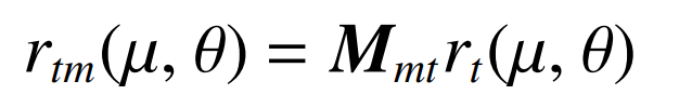
Where: Mmt is the conversion matrix from cutter head coordinate system St to machine tool coordinate system.
In the same way, the large wheel face cone equation of spiral bevel gear is transformed into the machine coordinate system, and its equation is:
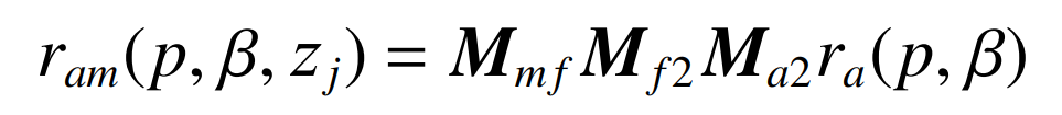
Where: is the transformation matrix from the coordinate system of face cone Mmf, Mf2 and Ma2 to the coordinate system of machine tool.
Therefore, in the machine tool coordinate system, the intersection line equation of the blade generation surface equation and the spiral bevel gear large wheel surface cone equation is:

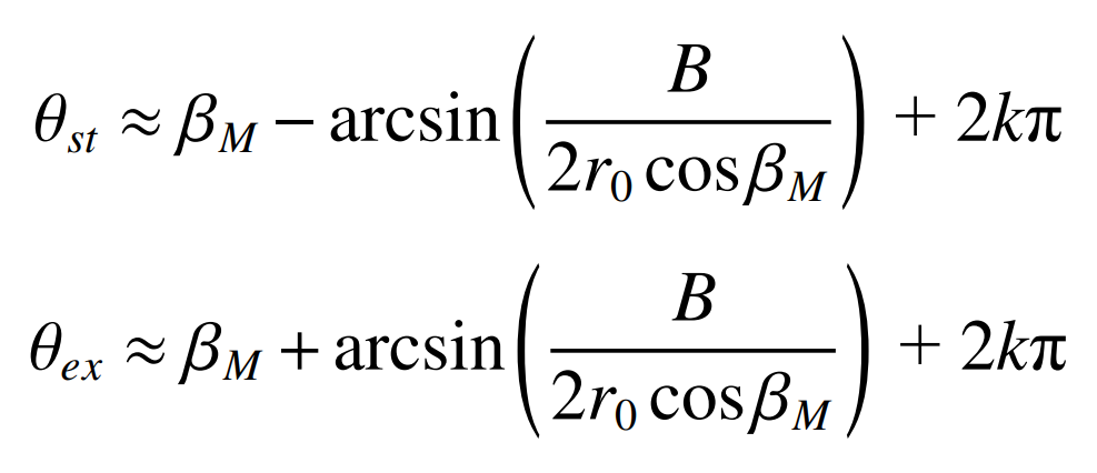
In order to obtain the cut in and cut out angle of the internal and external blades on the cutter head, that is, the internal and external blades cut the gear blank within the cut in and cut out angle range. Therefore, it is necessary to calculate the cut in and cut out angle of the internal and external blades. The relative position of the cutter head cut in and cut out the gear blank is shown in Figure 2.
Therefore, the cut in angle and cut out angle can be obtained as shown in the formula, where k is the number of turns the cutter head has turned.