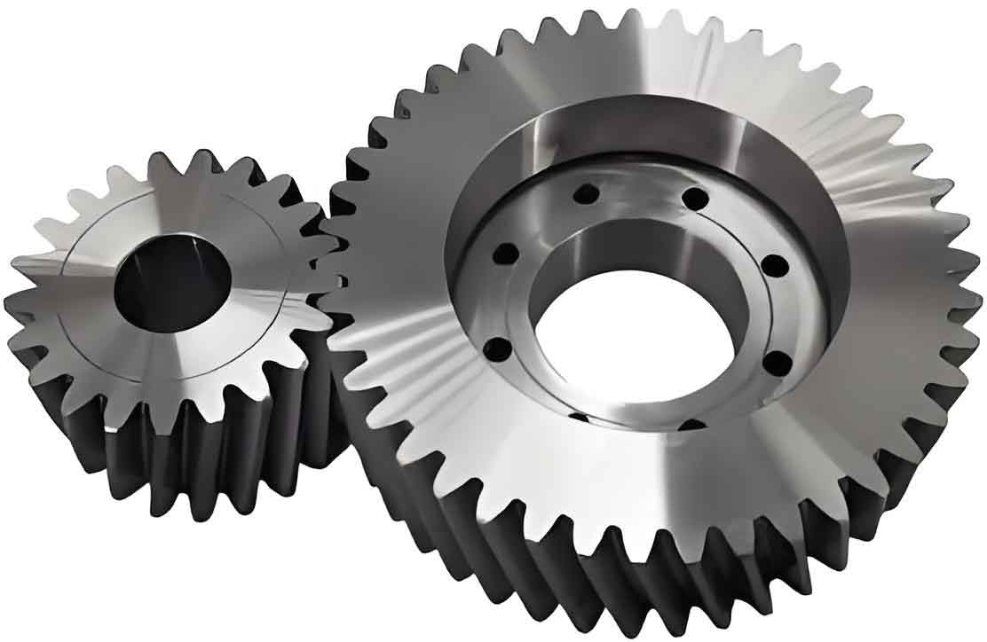
This paper proposes an efficient machining method for line-contact curvilinear cylindrical gears using existing six-axis CNC milling machines and single-edge face milling cutters. The approach addresses the challenges of high manufacturing costs and complex tooling requirements while ensuring theoretical line contact characteristics during meshing. A comprehensive mathematical model is established to guide the machining process, and numerical simulations verify the feasibility of the proposed method.

Mathematical Modeling of Tooth Surface
The geometric model of curvilinear cylindrical gears is derived based on differential geometry and meshing theory. The cutting edge geometry of single-edge face milling cutters is defined in coordinate system Sb:
$$r_b^g(u) = \begin{bmatrix}
\pm u\sin\alpha_n \pm \frac{\pi m}{4} \\
u\cos\alpha_n \\
0 \\
1
\end{bmatrix}$$
where g represents tool type (i: internal edge, o: external edge), αn is normal pressure angle, and m denotes module. The transition arc of cutting edges is expressed as:
$$r_b^g(\lambda) = \begin{bmatrix}
\pm\frac{\pi m}{4} \mp \tan\alpha_n(bm – \rho m + \rho m\sin\alpha_n) \\
\mp\rho m(\cos\alpha_n – \cos\lambda) \\
\rho m – bm – \rho m\sin\lambda \\
1
\end{bmatrix}$$
The coordinate transformation matrix from tool coordinate system Sb to machine coordinate system Sc is given by:
$$M_{c,b}(\theta) = \begin{bmatrix}
\cos\theta & 0 & -\sin\theta & -(R \pm \frac{\pi m}{4})\cos\theta \\
0 & 1 & 0 & 0 \\
\sin\theta & 0 & \cos\theta & -(R \pm \frac{\pi m}{4})\sin\theta \\
0 & 0 & 0 & 1
\end{bmatrix}$$
Key Process Parameters
| Parameter | Symbol | Value (mm) |
|---|---|---|
| Module | m | 4 |
| Cutter radius | R | 60 |
| Pressure angle | αn | 20° |
| Tooth number | Z | 31 |
Numerical Simulation and Verification
The meshing equation for tooth surface generation is derived as:
$$f(u,\theta,\psi) = \left(\frac{\partial r_1^{g,line}}{\partial \theta} \times \frac{\partial r_1^{g,line}}{\partial u}\right) \cdot \frac{\partial r_1^{g,line}}{\partial \psi} = 0$$
Numerical simulation results show maximum deviations between theoretical and machined cylindrical gear profiles:
| Tooth Section | Max Overcut (mm) | Max Undercut (mm) |
|---|---|---|
| Convex flank | 0.06 | 0.10 |
| Concave flank | 0.04 | 0.06 |
The mathematical model enables precise control of cylindrical gear tooth geometry, with coordinate transformation matrices ensuring accurate tool-workpiece relationship:
$$M_{1,c}(\psi) = \begin{bmatrix}
\cos\psi & \sin\psi & 0 & r_p(\sin\psi – \psi\cos\psi) + R_c\cos\psi \\
-\sin\psi & \cos\psi & 0 & r_p(\cos\psi + \psi\sin\psi) – R_c\sin\psi \\
0 & 0 & 1 & 0 \\
0 & 0 & 0 & 1
\end{bmatrix}$$
Conclusion
The proposed method demonstrates effective machining of line-contact curvilinear cylindrical gears using standard CNC equipment. Key advantages include:
- Elimination of specialized gear cutting machines
- Reduced tooling costs through standardized cutters
- Maximum profile deviation below 0.1 mm
- Applicability to various cylindrical gear sizes through parameter adjustment
This approach significantly lowers the technical barriers for manufacturing high-performance cylindrical gears with line-contact characteristics, enabling wider industrial adoption of curvilinear gear technology.
