
The machining simulation of helical gear turning is carried out by using VERICUT simulation software. Firstly, the virtual machining machine tool is established according to the actual machining requirements, then the three-dimensional model of the tool and workpiece to be machined is imported, and the NC code is written according to the relative position of the tool and workpiece in the machining process for virtual machining verification. This method can intuitively simulate the real helical gear turning process and tooth surface forming process, so as to verify the feasibility of helical gear turning process and the correctness of helical gear turning tool structure design.
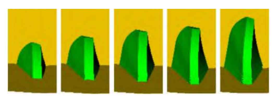
In order to verify the undercut and sharpening phenomenon of face gear, the inner and outer radius of the blank is set to the undercut and sharpening radius of face gear. The simulation process and results of helical gear turning process are given. It can be seen that with the processing, the tooth shape of the workpiece is gradually formed from the outside to the inside. The machining results are consistent with the expected assumptions, which verifies the feasibility of helical gear turning technology.
The simulation results show that the forming process of a single tooth slot of helical gear is shown in the figure. After the cutting edge of the tool cuts into the helical gear, the tool and the helical gear begin to carry out space generation cutting. The cutting and forming process of a single tooth groove is shown in Figure 1. It can be seen from the figure that the cutter and helical gear develop into motion to form the whole process of helical gear slot. In the process of cutting in, top edge and cutting out edge of the cutter from cutting in to cutting out, the left and right tooth surfaces forming helical gear slot are different, and the cutting out edge processes the surface tooth shape earlier than the cutting edge.
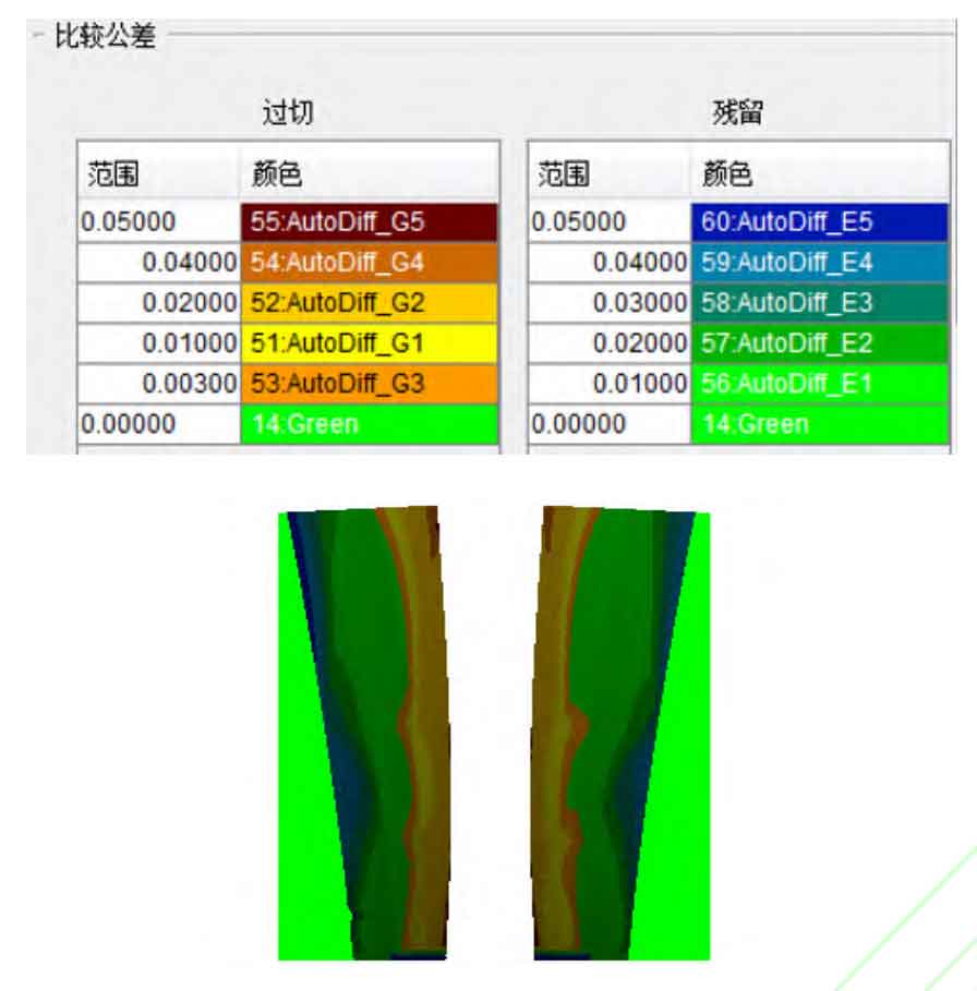
The “automatic comparison” function provided by VERICUT is used to analyze the tooth surface deviation between the gear after scraping and the standard surface gear. It can be seen from Figure 2 that there is a certain gap between the face gear model obtained by the simulation of helical gear scraping and the theoretical model, which is specifically manifested in the overcut at the tooth root of the face gear and the residue at the top of the face gear, and the maximum overcut and residue is about 0.05mm. The main reason for this result is that due to the existence of the rake angle of the helical gear scraping cutter structure, the cutting edge of the cutter is not the theoretical involute, and the rake angle of the cutter introduces a certain error to the machining.