The geometric modeling of helical gear turning tool is realized by using UG three-dimensional modeling software. In order to simplify the calculation, only five teeth of the whole helical gear turning tool are selected as the analysis object to obtain the final solid model of helical gear turning tool, as shown in Figure 1.

Using VERICUT software, the helical gear model at a certain time in the machining process can be obtained. In DEFORM software, the cutting condition of the tool at the next feed can be simulated by applying an axial displacement to the tool in advance. Figure 2 shows the cutting model at a certain time in the process of helical gear turning extracted from VERICUT software.

After setting the installation angle between the cutter and the helical gear, adjust the radial distance of the cutter along the helical gear to make the cutter as close to the helical gear as possible, so as to reduce the initial simulation calculation time. The position relationship between the cutter and the helical gear is shown in Figure 3.

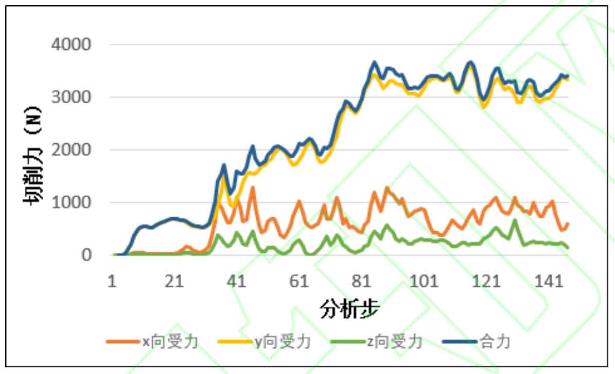
By analyzing the step history, the change law of tool cutting force in the process of helical gear turning is obtained, as shown in Fig. 4. It can be seen that the tool receives the largest force in the Y direction (radial direction of helical gear). In order to roughly estimate the average cutting force in the helical gear turning process, the average value of the tool cutting force after the analysis in step 80 is taken as the estimated value of the tool cutting force in the helical gear turning process. The average cutting force calculated here is 3247n.