
Abstract
This article delves into the derivation of a mathematical model for hobbing hypoid gears using the Spiroflex method, based on the coordinate system of a universal cradle-type gear-cutting machine. The mechanical settings of the universal cradle-type machine are converted to suit the coordinate system of a modern vertical six-axis gear-cutting machine. Subsequently, the mechanical coordinates of the six-axis gear-cutting machine are calculated, and a processing program for hobbing hypoid gears using the Spiroflex method is developed. Finally, VERICUT simulation software is utilized to simulate the hobbing process of hypoid gears, and the tooth surface errors between the simulated and theoretical gears are compared. The results indicate that both the tooth surface position error and tooth thickness error between the simulated and theoretical gears are less than 50 μm, validating the high accuracy of the mathematical model when implemented on a six-axis CNC gear-cutting machine for hypoid gear hobbing using the Spiroflex method.
1. Introduction
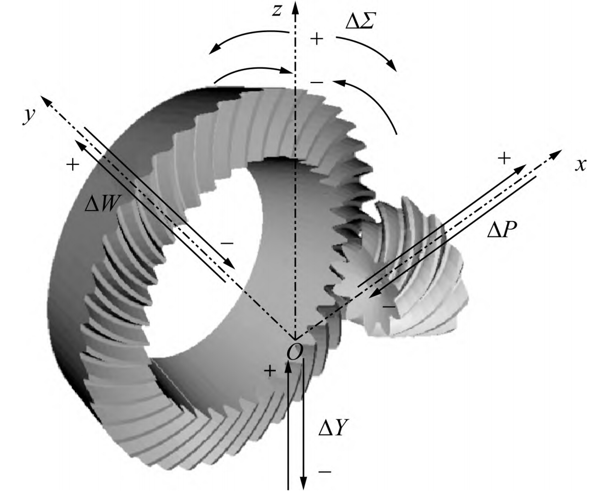
Hypoid gears, as a complex type of bevel gears in gear transmission, exhibit a series of advantages such as strong carrying capacity, high transmission efficiency, smooth transmission, low noise, and large reduction ratio. They are widely used as gears in automotive main reducers and serve as key components in automotive drive axles. Compared to spiral bevel gears, hypoid gears have an additional offset between the large and small wheels (Figure 1), which can effectively enhance the smoothness and off-road capability of vehicles during driving.
| Gear Type | Characteristics |
|---|---|
| Spiral Bevel Gear | No offset between large and small wheels, common in various mechanical transmissions |
| Hypoid Gear | Offset between large and small wheels, improved smoothness and off-road capability, widely used in automotive drive axles |
In recent years, scholars at home and abroad have conducted research on various aspects of hypoid gears, including tooth cutting design, processing methods, and installation errors. This article aims to establish a mathematical model for hobbing hypoid gears on a modern six-axis CNC gear-cutting machine using the Spiroflex method.
2. Mathematical Model for Spiroflex Hobbing of Hypoid Gears
2.1 Mathematical Equation of the Face Hobbing Tool
The face hobbing tool for hypoid gears consists of several bar-shaped cutting edges, with a maximum of three types: inner, middle, and outer cutting edges (Figure 2). The middle cutting edge is mostly used for rough cutting, the inner cutting edge for cutting the convex surface of the gear, and the outer cutting edge for cutting the concave surface.
The cutting edge of the face hobbing tool is divided into a straight edge and a rounded edge.
The position vector of the cutting edge in coordinate system Sl is represented in homogeneous coordinates as:
T )
The cutting edge consists of a rounded edge rlf(u) and a straight edge rll(u), with the equations derived as follows:
For the straight edge:
xll(αF;u)=±usinαF
zll(αF;u)=ucosαF
For the rounded edge:
xlf(αF;ρo;hr;u)=±(xcf−ρocosu)
zlf(αF;ρo;hr;u)=zcf+ρosinu
Where (xcf,zcf) represents the coordinates of the center of the fillet, ρo is the fillet radius, hr is the height of the rounded edge, and u is the parameter along the cutting edge.
Table 1: Parameters of the Cutting Edge
| Parameter | Description |
|---|---|
| αF | Flank angle of the cutting edge |
| u | Parameter along the cutting edge |
| ρo | Fillet radius |
| hr | Height of the rounded edge |
| xcf | X-coordinate of the fillet center |
| zcf | Z-coordinate of the fillet center |
3. Simulation and Verification
Using VERICUT simulation software, the hobbing process of hypoid gears is simulated, and the tooth surface errors between the simulated and theoretical gears are compared. The results demonstrate that both the tooth surface position error and tooth thickness error are less than 50 μm, verifying the high accuracy of the mathematical model.
4. Conclusion
This article establishes a mathematical model for hobbing hypoid gears using the Spiroflex method on a modern six-axis CNC gear-cutting machine. The model is verified through simulation, showcasing its high accuracy. This research contributes to the advancement of hypoid gear manufacturing technology, with significant practical implications for improving the performance and efficiency of automotive drive axles and other mechanical transmissions.