The tooth profile of non orthogonal helical gears is usually meshed through point contact, transmitting the transmission power of cross axis helical gears, and has excellent transmission performance and torque splitting effect, making non orthogonal helical gears widely used in fields such as automotive differential mechanisms, helicopter reducers, robot structures, conveyor drive systems, etc.
Domestic and foreign scholars have conducted research on the contact characteristics of helical gear pairs. Liu et al. established an accurate meshing model for helical gear pairs and studied the influence of workpiece clamping device errors on the meshing characteristics and tooth surface geometry of end face hobbing hypoid gears. Based on the characteristics of surface meshing transmission, Yang Zhuxi et al. established a non orthogonal helical gear profile modification tooth surface model, derived an analytical equation for contact stress, and analyzed the contact stress of helical gears through finite element software. The results showed that the finite element simulation results were highly consistent with the derived contact stress results. Li Shixuan et al. established a dynamic model of involute helical gear pairs through conjugate tooth surface contact trajectory, and conducted simulation using numerical analysis method to study the influence of various parameters on contact characteristics. Ma Dengqiu et al. designed and developed the structure of circular arc tooth profile cylindrical gears, and compared the transmission characteristics of this structure with traditional helical gears through finite element analysis. The study showed that the designed circular arc gears have better transmission performance. Zhu Dongwen et al. established a mathematical model for helical gear meshing with axis deviation, which considers the meshing effect of multi tooth contact pairs and analyzes the influence of different axis deviation angles on the contact characteristics of helical gears. Chen Yan et al. studied the tooth contact characteristics of variable tooth thickness involute gears under different loads, and the results showed that shaft intersection angle and axial offset are important factors affecting the contact state of the transmission pair. This conclusion provides a reference basis for the contact analysis of involute gear transmission.
Based on the above research results, ZHY Gear proposed a new theory for the design of helical gear transmission based on curved contact elements. The purpose of proposing this design theory is to improve the load-bearing capacity and transmission characteristics of orthogonal helical gear transmission. Through modeling and simulation, the contact characteristics of non orthogonal helical gear pairs are studied, providing theoretical support for the structural design of non orthogonal helical gear pairs.
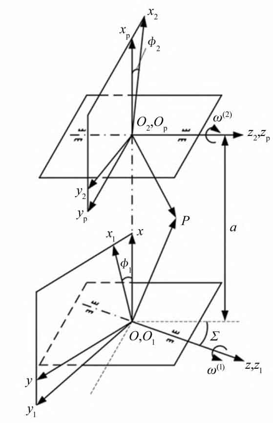
The non orthogonal helical gear model established by ZHY Gear is shown in Figure 1. The fixed coordinate system is S (O-x, y, z), Sp (Op xp, yp, zp), and the active coordinate system is S1 (O1-x1, y1, z1), S2 (O2-x2, y2, z2), with variables ω (1) And ω (2) is the angular velocity, φ 1 and φ 2 represents the rotation angles of small gear 1 and gear 2, respectively, Σ Is the angle between the two axes, a is the center distance, and P is the contact point.
Assuming spatial curves Γ 1: r1=x1 (t) i1+y1 (t) j1+z1 (t) k1 is located in coordinate system S1, where r1 is the polar coordinate vector of the contact point in coordinate system S1. Based on the relationship between the helical gear pairs established in Figure 2, the relative velocity at the contact point P can be obtained as:
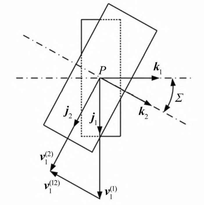

In the formula: v (12) 1 is the relative velocity at the contact point P; X1, y1, and z1 are the coordinate values in the x, y, and z directions in coordinate system S1, respectively; T is the curve arc length parameter; I21 is the transmission ratio, i21= φ 2/ φ 1; I1, j1, and k1 are the normal vectors in the x, y, and z directions of polar coordinates, respectively.
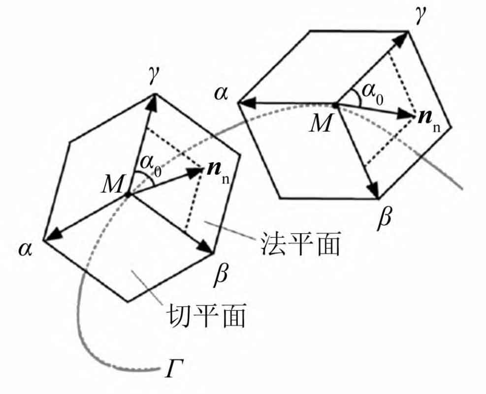
From Figure 3, it can be seen that the normal vector at contact point M can be represented as nn=un β + Vn γ, Variable n β And n γ Represent the main normal vector and the secondary normal vector respectively.
Spatial curve Γ 2: r2=x2 (t) i2+y2 (t) j2+z2 (t) k2, which is related to the spatial curve Γ 1 conjugate, spatial curve Γ The coordinate value of 2 can be calculated using the formula:
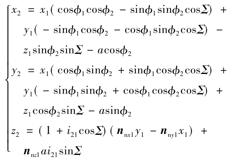
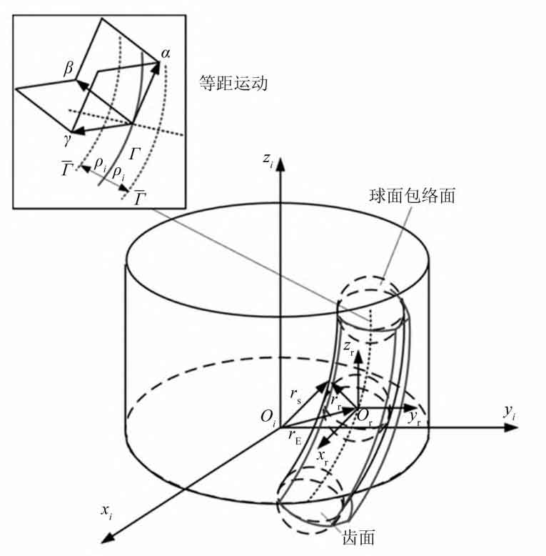
In the formula, x2, y2, and z2 are the coordinate values in the x, y, and z directions of the coordinate system S2, while nnx1, nny1, and nnz1 are the normal vectors in the x, y, and z directions, respectively. By using the equidistant envelope method and the conjugate curve expression, the parameter expression of the action surface of the helical gear tooth profile is studied, as shown in Figure 4. Corresponding equidistant curves Γ I through r Γ I=ri ± ρ In0ni (i=1,2) is solved, where r Γ I is the coordinate vector of the equidistant curve, ri is the polar coordinate vector of the contact point, and n0ni is the unit normal vector, ρ I is equidistant. Therefore, the general equation for deriving the tooth profile of helical gears is:
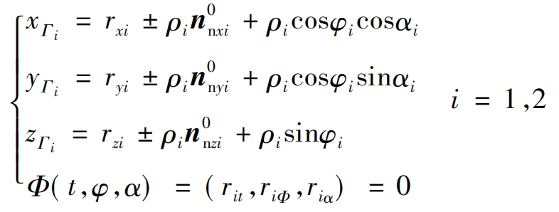
In the formula: x Γ i. Y Γ i. Z Γ I represents the coordinate values of equidistant curves in the x, y, and z directions, respectively; Rxi, ryi, and rzi are the coordinate values of the contact point in the x, y, and z directions, respectively; N0nxi, n0nyi, and n0nzi are the normal vectors of the contact point in the x, y, and z directions, respectively; φ I is the rotation angle of the contact point; α I is the offset angle of the contact point; Φ (t, φ,α) Is the generalized curve polar coordinate equation, where t is the arc length parameter of the generalized curve, φ The rotation angle of a generalized curve, α Is the pressure angle of the generalized curve; Rit, ri φ、 Ri α These are the generalized parameters corresponding to the contact points.
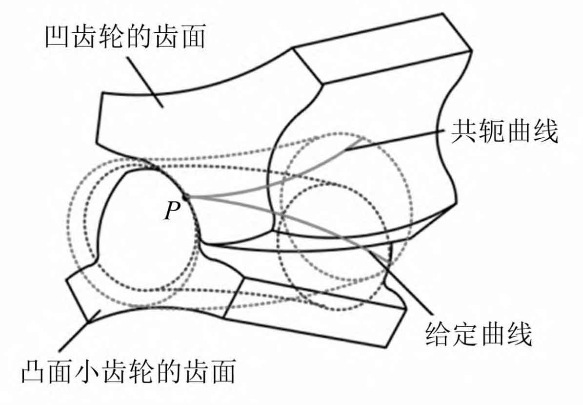
From this, the surface of the sphere can be represented as rsi( ρ ICOS φ Cos α,ρ ICOS φ Sin α,ρ Isin φ) , Among them φ ∈ [- 0.5 π, 0.5 π], α ∈[ 0, 2 π]. A convex concave tooth profile was designed based on the top and root surfaces of the helical gear, and the meshing model of the helical gear tooth profile is shown in Figure 5.
