
As we all know, the tooth surface of spiral bevel gear is a very complex spatial surface. Using coordinate measuring machine to measure the tooth surface shape of spiral bevel gear is mainly to set the measurement coordinates in advance, and then measure point by point. Increasing the number of measurement points is an effective method to improve the measurement accuracy, but with the increase of measurement points, the optimization of measurement path is particularly important. When the coordinates of measurement points are determined, the optimization of measurement path directly affects the measurement efficiency, especially when the distribution of measurement points is uneven. In addition, when the measurement path planning is wrong, it will inevitably lead to the collision between the probe and the workpiece. It can be seen that the measurement path is essential, which can not only reduce the empty operation of the measurement process, but also complete the measurement work with the shortest path without the collision between the probe and the workpiece, so as to improve the measurement efficiency. Figure shows the schematic diagram of the tooth surface measurement path of spiral bevel gear studied.
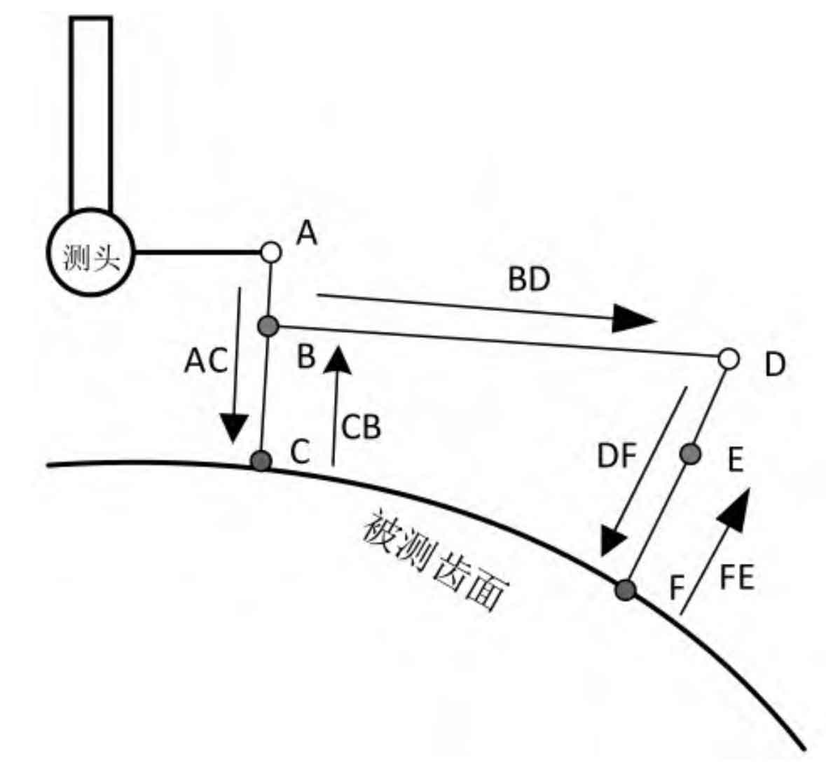
As shown in Figure, the measurement process with CMM can be roughly divided into three processes: reaching the positioning point, approaching the measurement point and returning to the fallback point. First, the probe reaches the specified first positioning point a at a faster speed, and then moves to point C in the normal direction of measuring point C, as shown in the path of figure AC; After completing the measurement, return to the fallback point B, as shown in Figure CB path. Now, complete the measurement of a measuring point. After that, the probe moves to the next positioning point D, measuring point F and fallback point e to complete the corresponding measurement work. Therefore, it can be deduced that when the probe completes the measurement of a measurement point, the moving distance is:
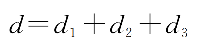
Where D1 is the distance from the positioning point to the target measurement point; D2 is the distance from the measuring point to the fallback point; D3 is the distance from the fallback point to the next positioning point.
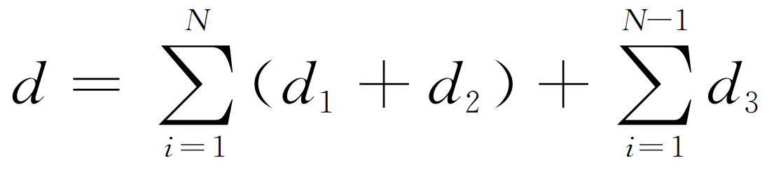
If the sum of measurement points is n in the whole spiral bevel gear tooth surface measurement, the measurement path of spiral bevel gear tooth surface can be expressed as:
Through the above analysis, it can be found that D1 and D2 are fixed values regardless of the selection of measurement points, that is, the measurement path of spiral bevel gear tooth surface is only affected by D3. Therefore, the optimization objective function of spiral bevel gear tooth surface measurement path can be further expressed as:
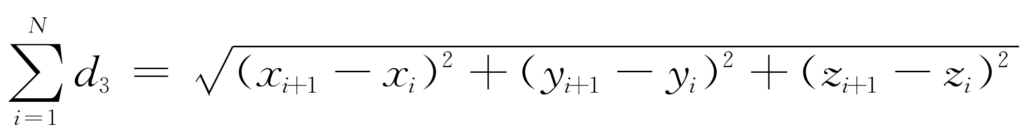
Where, (Xi, Yi, Zi) and (Xi + 1, Yi + 1, Zi + 1) are the coordinate values of the I and I + 1 measuring points respectively.