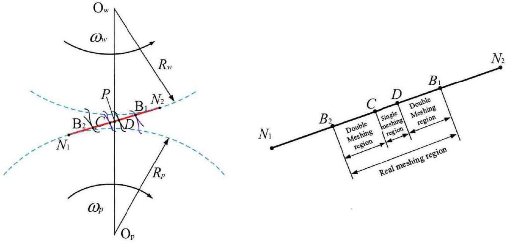
According to the spatial meshing principle of involute spur gear, when a pair of standard involute tooth profiles are meshed, the meshing points moving along the tooth profile are scattered on the internal common tangent (ideal meshing line) between the two base circles of the gear pair, as shown in Figure.
In figure (a), take the meshing point B2 near the root of driving gear and the top of driven gear as the initial meshing point, that is, the root of driving gear P pushes the top of driven gear w to whistle on the meshing line B2. At this time, the other two pairs of teeth adjacent to the driving / driven gear mesh at point D. It shows that the gear pair is in the state of double tooth meshing. In order to describe the motion state conveniently, the two pairs of teeth meshed at point D are set as the first pair of meshing teeth, while the two pairs of teeth meshed at point B2 are set as the first pair of meshing teeth, and so on.
When the first pair of teeth begin to mesh from point B2 to point C, the 0 pair of teeth mesh from point d to point B1, that is, the driving gear top pushes the driven gear root, and the two meshing teeth are about to be out of mesh. The first pair of teeth continue to drive along the meshing line, and only the first pair of teeth undertake the meshing transmission function from meshing point C to meshing point D. When the first pair of teeth meshed to the point, the new second pair of teeth began to mesh at B2. With the continuous meshing, the first pair of teeth disengaged at B1. At this point, a pair of teeth begin to mesh from B2 to B1, and complete the full tooth profile meshing from root meshing to top meshing. It can be seen that the actual meshing line distance of gear transmission is a line segment, so this line distance is called the actual meshing line of gear transmission, as shown in Figure 1 (b).
According to the above description of the meshing transmission process of a pair of gears, on the actual meshing action line, taking the meshing of the first pair of teeth as the analysis reference object, from the meshing at B2 point to the meshing at B1 point, the gear pair respectively experiences the meshing B2C segment in which the meshing of the first pair of teeth coexists, the meshing CD segment in which the first pair of teeth mesh alone, and the meshing db1 segment in which the meshing of the first pair of teeth coexists with the meshing of the second pair of teeth Segment, i.e. double single double Meshing Effect (as shown in figure (b)). It can be seen that for a pair of ordinary spur gear meshing pair, in order to ensure the smoothness of meshing, the range of its coincidence degree is generally 1 ﹤ ε ﹤ 2.
According to the geometric relationship of fixed-point engagement shown in figure (a) and the geometric mathematical derivation relationship, the distance length of each relevant line segment can be derived, as shown in Formula 1. In order to facilitate the later simulation analysis, all the calculation parameters are expressed by the basic parameters of gear involute (such as modulus, number of teeth, pressure angle, working angle, etc.), so Formula 1 can be simplified into formula 2 by the basic parameters.

Where:
Rap, raw – radius of driving and driven gear addendum circle, m;
RBP, RBW – base circle radius of driving and driven gears, m;
RP, RW – radius of graduation circle of driving and driven gears, M.

Where:
M-gear module, m;
A-gear pressure angle, RAD;
ZP, ZW – number of teeth of driving and driven gears;
AAP, AAW – driving and driven addendum meshing angle.

Formula 3 is the expression formula of the pitch of standard involute gear. By dividing the actual meshing action line and pitch PN, the coincidence degree of standard involute gear transmission can be obtained as follows:
At the same time, according to the geometric relationship of the line segments in the single double meshing zone as shown in Fig. (b), the length of the line segments in the single meshing zone and the line segments in the double meshing zone can be deduced as follows:


