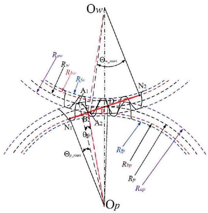
In order to further calculate the meshing interval expression of gear in a single period from meshing in to meshing out and the relationship between each single double meshing interval and rotation angle. Figure 1 shows the detailed meshing geometric diagram of the spur gear pair at the initial limit position at the negative point. Taking the driving gear P as an example, the line between the endpoint N1 of the ideal meshing action line and the center op of the circle is taken as the datum reference line, and the line between the center line A1 and op of the tooth top of the meshing gear is taken as the rotation object line, so that the initial included angle ∠ n1opa1 between the two lines is defined as Θ P_ At this time, the initial angular variable Θ P = 0. According to the geometric relationship of meshing, Θ P is deduced_ The expression of start is:
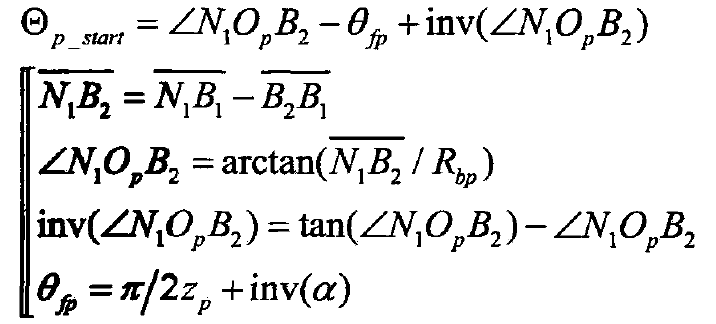
Where: θ FP – single tooth root arc angle of driving gear, rad.
Similarly, the driven gear w takes own2 as the reference datum line, owa2 as the rotation object line, and ∠ n2owa2 is defined as 0W_ The expression is: start
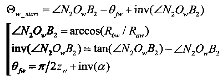
Where: θ FW – single tooth root arc angle of driven gear, rad.
The detailed meshing geometry diagram of spur gear pair at the end of meshing is drawn in Fig. 2. For driving gear P, the helix OPA1 at the end of meshing becomes opa11, and the meshing end angle ∠ n1opa11 is defined as Θ P_ According to the geometric relationship of meshing, Θ P is deduced_ The expression of end is:
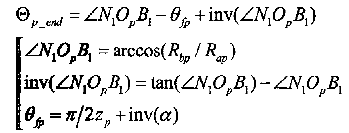
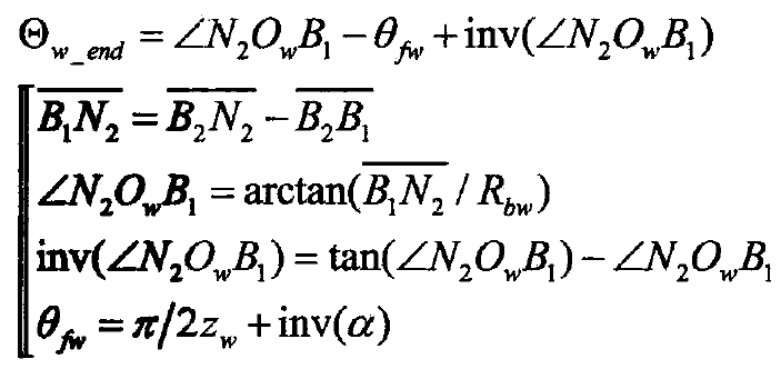
Similarly, ∠ n2owa22 at the end of meshing position of driven gear W is defined as Θ W_ The expression is: end

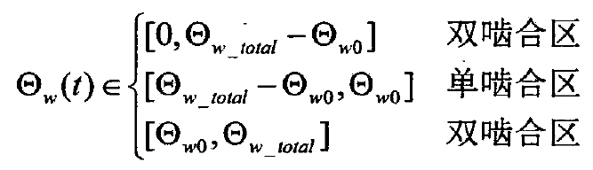
According to the detailed geometric description of the two limit states of meshing in and meshing out of the gear pair, the single tooth of the driving and driven gears is meshed from point B2 to point B1, and the total rotation angle increment or decrement of the gear in this meshing process can be expressed as a formula. When the meshing point of tooth profile changes from point B2 to point D, the change of meshing angle of driving gear P is just the tooth pitch, and the arc angle of tooth pitch is 0.0p 0 = 2 π / ZP. According to the double single double meshing alternate action shown in Fig. 3 and the boundary meshing position condition, the angle change boundary of single double regions can be deduced. Assuming that the rotation angle Θ P is a function of time Θ P (T), the derived boundary can be expressed as a formula.

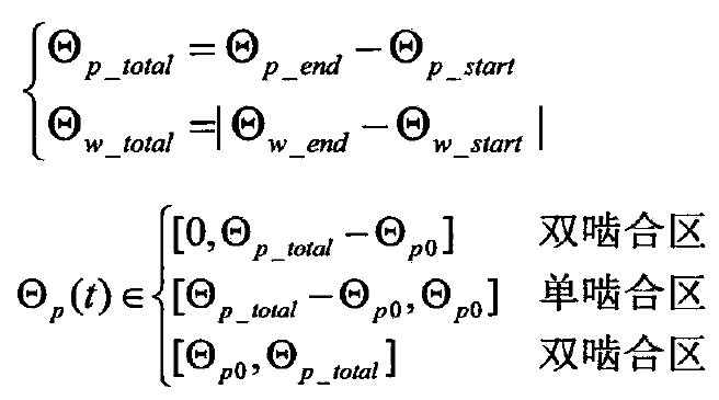
In the same way, for the driven gear W, the boundary of the rotation angle area is derived as a formula.