At present, the focus of mining equipment is to lightweight, and the structure of mining mechanical reducer has a significant impact on the lightweight of the whole machine [1-2]. The size of the spiral bevel gear directly determines the structure and overall quality of the mine reducer [3-5], so reducing the structural size of the spiral bevel gear has an important impact on reducing the quality of the gear, bearing pedestal and case [6-7]. The results show that the bending strength and contact strength of gear teeth can be improved by increasing the pressure angle properly, but if the pressure angle on both sides of gear teeth is increased, the tip of gear teeth will become sharp. In the operation process of mine reducer, the working tooth surface is mainly loaded [10-11]. Therefore, the comprehensive influence of pressure angle on the performance of gear teeth is designed to use a large pressure angle on the working tooth surface and a standard pressure angle on the non working tooth surface, which can not only avoid the tooth tip becoming sharp, but also make full use of the advantages of a large pressure angle to ensure the same bearing capacity, The module of spiral bevel gear is reduced, so the volume and mass of gear, bearing seat and case are reduced. The whole machine has multiple reducers, so the design has obvious effect on the lightweight of the whole machine.
In this paper, based on the meshing mechanism of spiral bevel gear, the design method of double pressure angle asymmetric spiral bevel gear of mine reducer is put forward. According to the cutting principle of spiral bevel gear, the asymmetric gear cutter is designed and manufactured, and the double pressure angle asymmetric spiral bevel gear is manufactured, Through the calculation, simulation and experiment of the load-carrying capacity of the unsymmetrical spiral bevel gear by the analytical method, the finite element method and the closed gear test-bed, it is proved that the load-carrying capacity of the unsymmetrical spiral bevel gear is not less than that of the symmetrical gear. Compared with the original structure of the mine reducer, the lightweight effect is obvious.
Due to the different pressure angles on both sides of the bevel gear, the section at the tooth root becomes thicker, the section at the tooth top becomes thinner, and the thickness of the working tooth side and the non working tooth side, the fillet at the tooth top and the fillet at the tooth root have changed. Therefore, it is necessary to study the meshing principle of the bevel gear.
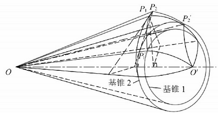
The double pressure angle asymmetric spiral bevel gear has two different base circles, the two base cones have two different meshing planes, which are pure rolling along their respective meshing surfaces. The two base cones have a common pitch cone, and the two pitch cones of a pair of double pressure angle asymmetric spiral bevel gears are tangent to each other. As shown in Figure 1, the base cone op’1o ‘of the working tooth surface and the non working tooth surface op’2o’ do pure rolling on the two meshing planes, and the distance between the moving points P1 and P2 and the top o of the base cone is a fixed value, so the moving tracks drawn on the sphere by the moving points P1 and P2 are spherical involutes p1p’1 and P2P’2. Therefore, the tooth profile of double pressure angle spiral bevel gear is composed of a series of gradually offset spherical involutes formed by points on OP1 and op2. In Figure 1, two spherical arcs p1p’1 and P2P’2 are on the back cone of the bevel gear at the same time.

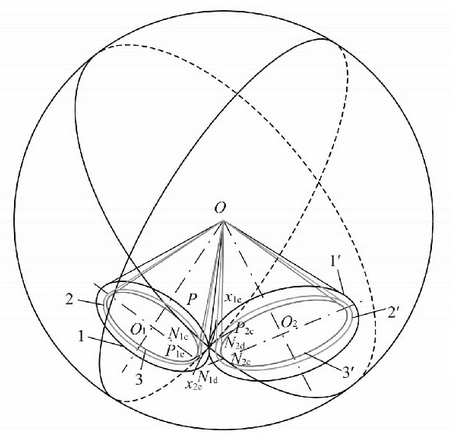
The formation principle of the spherical involute of the large end tooth profile of a pair of meshed double pressure angle asymmetric spiral bevel gears is shown in Figure 2. The two bevel gears have four base cones, namely, the non working tooth surface 2, 2 ‘and the working tooth surface 3, 3’, and the two base cones of each bevel gear have a joint cone.

Two pitch cones 1,1 ‘are tangent to OP, oo1 and oo2 are the central axes of the two bevel gears; O is the apex of the cone, which is also the meshing intersection point of a pair of bevel gears, and OP is the radius of the sphere. The intersection curve of the two pitch cones and the sphere is the pitch circle of the two bevel gears, and the tangent point of the two pitch cones is p.
There is a base cone in the asymmetric spiral bevel gear, and the circle that the two base cones intersect with the spherical surface is the base circle of the two gears. The subscript c represents the non working tooth surface, D represents the working tooth surface, Op represents the common section on1cpn2c of the two base cones 3,3 ‘, Op represents the common section on1dpn2d of the two base cones 2,2’, on1cpn2c and on1dpn2d are the two normal planes of the tooth profile of the working tooth side and the non working tooth side. In the same way, the p-points of the spherical curve n1cn2c will form the spherical involutes p1cpx1c and p2cpx2c on the sphere. Similarly, the p-points of the spherical curve n1dn2d will form the spherical involutes p1dpx1d and p2dpx2d on the sphere, The four spherical involutes here are the theoretical spherical involute profiles of the active and passive gears on the working side of the unsymmetrical spiral bevel gear pair.
