Face gear transmission is a kind of gear transmission in which the cylindrical gear and the bevel gear are meshed. The face gear is made of the same or similar cutters with the same size and the involute cylindrical gear in the meshing. The unique characteristics of face gear in diffluence confluence drive make it have potential advantages in the field of aviation, especially in the application of new type combat helicopter. The contact area of face gear tooth surface refers to the superposition of contact lines on the tooth surface of face gear mesh. The size, shape and position of the contact area not only reflect the manufacturing accuracy of a single gear, but also reflect the installation and transmission accuracy of the gear pair. It is a comprehensive technical index that affects the bearing capacity, service life, transmission quality and efficiency, noise and other comprehensive technical indicators of the gear pair transmission. Therefore, the contact area of the tooth surface is usually regarded as an important basis for evaluating the dynamic performance of the gear transmission. At present, experimental research has been carried out on the meshing principle, contact strength, bending strength, cutting and grinding of face gear at home and abroad. Litvin et al. Studied the face gear transmission and the generation of tooth surface, machining method, structural stress and finite element modeling analysis of face gear, and developed the point contact theory of face gear transmission. Li zhengminqing et al. analyzed the bearing contact of point contact surface gear drive. Luo Taijing analyzed the form of the contact spot on the tooth surface of the cylindrical gear, studied the relationship between the contact spot on the tooth surface and the transmission noise, and adopted the corresponding quality control method according to the cause of the contact spot on the tooth surface. Hou Yin et al. Studied the contact characteristics of the tooth surface in the orthogonal face gear transmission, and obtained the change rule of the main curvature at the contact point of the cylindrical gear and the orthogonal face gear. However, there are few reports about the relationship between the contact area of the face gear and the number of teeth and transmission ratio of the cylindrical gear at present. For this reason, the author studies the influence of the number difference of teeth, transmission ratio and manufacturing accuracy of the cylindrical gear on the contact area of the face gear through the simulation of the contact area of the face gear and the contact detection experiment of the face gear.
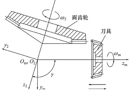
The surface gear is processed by the involute cylindrical gear cutter by the generating method, and the processing diagram is shown in Fig. 1. When the surface gear is machined by the generating method, if the cutter tooth surface moves relative to the surface gear according to the given transmission ratio, the enveloping surface of the slow cutter tooth surface is the tooth surface of the surface gear. The tooth surface equation is derived from the tooth surface equation of the cutter according to the meshing principle of the gear.

The derivation of the tooth surface equation of face gear can be summarized as follows:
(1) In the coordinate system SM consolidated with the tool, the tool tooth surface Σ m is determined;
(2) The coordinate of tool tooth surface in SM is transformed into the coordinate frame S2 consolidated with the face gear to form a tool surface group according to the change of tool angle m;
(3) In the S2 coordinate frame, the tooth surface Σ 2 of the face gear is calculated by the combination of the surface group and the meshing equation.
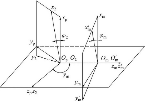
The relationship of coordinate systems in the process of face gear machining is shown in the figure.

The description of tooth contact in face gear meshing
The equation of tool involute tooth surface Σ m is as follows:

Where: RBM is the base circle radius of tool involute; um is the axial parameter of a certain point of tool tooth surface Σ M. According to the above steps, coordinate transformation is carried out for the tool tooth surface Σ m, and the equation of the tooth surface Σ 2 of the face gear is obtained as follows:

Where: 2 (28) i2m M. Another tooth surface equation of a face gear tooth can be obtained by changing the symbols of m and M.
