
As shown in figure (a) and (b), the flow direction and size distribution of metal in X and Y directions when simulating step 44, figure (c) and (d) are the flow direction and size distribution of metal in X and Y directions when simulating step 65, and figure (e) and (f) are the flow direction and size distribution of metal in Z direction when simulating step 50 and step 65.
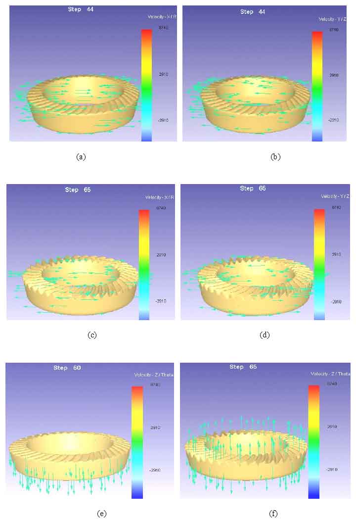
The effective analysis of metal flow law is helpful to predict the defects in the tooth profile of spiral bevel gear in actual forging production. It can be seen from the figure that when the workpiece is simulated to step 44 (initial deformation), the metal flow size in the X and Y directions is basically similar, and there is a uniform flow trend distribution in the direction. At this time, it belongs to the upsetting stage in the initial deformation (in the upsetting stage, the movement direction of the die is perpendicular to the metal flow direction), as shown in figures (a) and (b). In the Z direction, the metal shows a uniform downward flow trend, which belongs to the extrusion stage at the initial stage of deformation (in the extrusion stage, the movement direction of the die is parallel to the flow direction of the metal), as shown in figure (e).
As the punch of the die moves downward to compress the blank, the diameter of the spiral bevel gear blank gradually increases, and the metal begins to flow from the upper part of the blank to the bottom and from the center to the circumference, as shown in figure (e). At this stage, the pressure value will also increase with the increase of blank metal deformation. The blank metal of spiral bevel gear is in the state of high temperature and three-dimensional compression at this stage.